Diode matching test Jig for diode limiters

GroupDIY Audio Forum

Help Support GroupDIY Audio Forum:

This site may earn a commission from merchant affiliate links, including eBay, Amazon, and others.

maxwall

Well-known member
Joined
Nov 17, 2004
Messages
1,134
33609 and TG limiters , and others requiring matching. No need to go
and buy a elaborate tektronix curve tracer.

Standard Diode matcher
diodemch.gif


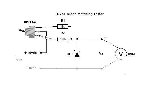
Another method for your madness - see below

Zener matcher
Take 12V stabilized power supply, piece of breadboard, IC socket, two resistors say 10k and 1k, and spdt switch.
Connect voltmeter across zener, measure voltage with 10k in series to zener, switch 10k to 1k, measure, write this down, next....
Actually, you don't need to match 4, but 2 pairs.

Zener Jig , illustration here


DiodeDUT_1.jpg
 
Is method 2 is for zeners only? In method 1, is one diode installed at a time? I am trying to match for diode bridge type compressors, so I think I need some idea of how they respond over a range??
Thanks for this!
 
Method #1 , I assume installing  both diodes then compare voltages on each diode with VOM reading.
take reading across anode & cathode for each device. Again , I'm thinking the voltage drop accross each one should
be the value your trying to match.

But I stand to be corrected , if someone knows better.
 
OK, so I built the test jig #1. Full rotation of the pot gives me +2 VDC (on one end) and +3 VDC (on the other end.
As I am ignorant here, what does this mean? What should I be looking for? :-\
 
I believe you are trying to get 0 volts, on figure 1--as in same drops in both branches= matched, the pot is 'prolly there so you can dial in something within the meters resolution, but is probably not essential. just a I limiting 1k or whatever

method 2 could work for regular diodes but need to flip diode and maybe up the resistance: 10k &100k?
 
This is cool, what about OA202 diodes you supplied with the TG boards, those aren't matched? And to match them I'd need a pile to select from? Maybe you would offer matched diodes?
::)
 
I believe that is method 2 as posted above... ;)
I mis-reported results before, it should read mV, not volts. At this point I have adjusted the pot so that it just crosses over from 0.02 Amps to 0.01 amps draw, then compared several diodes to one until I found a set that measured the same, then put that set in and am reading down to +/- 0.5 mV.
This is measuring 1N4153s
Any ideas?
 
After experimentation I can report method 1 works well, the surprise is how many diodes it took going through to match. Out of a batch of "close tolerance" units maybe 10% match to within +/- 1 mV of a median value, I came up with 2 sets out of 100 that matched exactly.
Acceptable matching tolerance, anyone?
 
OA202 are not specified for matching in documentation that I have come accross thus far

As for 1N751A, different story , matched pairs needed here because this is the
zener bridge where matching is specified in documentation.

1N4153 -33609
1N751A - TG

Neilsk,

(Jig #1) where did you find yourself with 5K pot setting for initial testing of the matched sets you
found. Did the Jig #1 require the use of two meters or just one ?

Since this is a tesing jig for a broad range of diodes , it might be nice to know test settings for certain
types of diodes like 1N4153 etc... example,  5K pot set at 2.5K ohm , 1k ohm ,  etc ...
 
> I assume installing  both diodes then compare voltages on each diode with VOM reading.
> Full rotation of the pot gives me +2 VDC (on one end) and +3 VDC (on the other end.
As I am ignorant here, what does this mean? What should I be looking for?


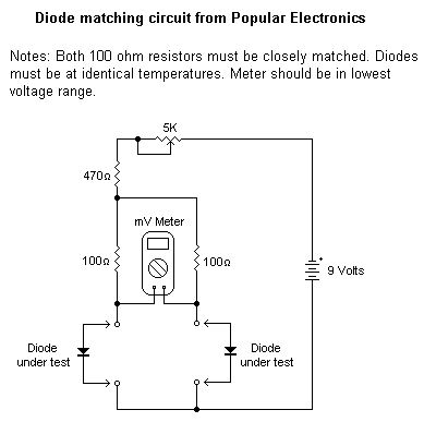
LOOK at the picture. There are two resistor-diode legs. There is a meter from diode to diode. What happens if all parts MATCH? The meter reads ZERO.

So if you find a zero-reading, the diodes match AT the current set by battery and resistors and some little stuff.

> it might be nice to know test settings for certain types of diodes like 1N4153 etc...

THINK. What does the compressor DO with the diodes? There's several methods. Most run the diode from small or zero current up to a "high" current. The "high" current will be nowhere near the diode's rated current. 1mA to 10mA (maybe MUCH less) on common "100mA" diodes. Diode is diode. Nearly ANY diode can be used. You need to look/see what current range the COMPRESSOR is applying to the diodes.

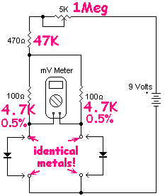
If you have a good current meter, break the feed TO the diodes and insert current meter. Force the compressor from 1dB to 20dB gain reduction. Note currents. Now re-rig your first picture so the 9V, 5K, 470, and ~~0.5V diode drop cover the same range. More likely 100K audio plus 5K fixed. Maybe much higher. Put in your diodes, turn the pot, watch for least-difference over the whole current range.

33609 runs maybe zero to 23V through a couple K ohms, say from zero idle to 5mA-10mA MAXED-out. The network feeding the bridge is about 5K. So diode current of less than 30/5000 ma or 0.006mA is not important. And diode current 10 times higher is 20dB gain reduction, a LOT. I'm thinking the important range is say 0.01mA to 0.1mA.

We see that the PopElectronics diode tester is NOT scaled for audio compressor diode testing. What a shock.

With 9V battery and 0.5V diode, we want 8.5V/0.01mA to 8.5V/0.1mA, or 850K to 85K. Put a 1Meg pot in series with 47K.

The "100 ohm" test resistors probably should be more like bridge impedance, 5K.

We are looking at MILLI-VOLT errors. Thermocouple effects will exceed a milliVolt. Diode sockets (and leads) should all be identical metals and temperature.

LFMoE.gif


Now insert diodes, turn the pot, watch the meter. Note if error is "small". If not, try another diode.

What is "small"? Diode bridge signal levels are near 60mV. If you turn the pot and diode difference is as bad as 50mV, and compressor time constant is rapid, the attack THUMP will blow your woofers. If diode voltage difference is 10 times less, 5mV, the thump will not be noticed on most program material. Golden-ears will want better than 5mV difference. 1mV difference is probably futile.... real-world drift will be this bad, that's just over-fussy and a time-sink. 2mV or 3mV is beauty.
 
PRR,

Excellent analysis, and you have demonstrated that it is important to set up a jig that
will exhibit close to actual operating conditions and known circuit constants when attempting to
match devices, which makes a lot of sense.

one question and correct my interpretation,  if needed.  If the diodes matched in one version of the test jig with
different resistor values would they not be the same matched diodes in another version with yet different
resistor values.  Because,  fundamentally,  the diodes have not changed their own characteristics , they are still
constant no matter what workable values are chosen for the test Jig resistors.

let me put it another way

Its like saying that..... if you have a pair of matched diodes , will they behave differently if asked to operate in test Jig-A
as opposed to test Jig-B ? , (this is assuming the test jig resistor values are not wildly different)

My understanding is no , they should still behave the same , but maybe test voltages/currents will be a
bit different , yet the devices should still match in the test Jig.
 
1N4153 seem to be a bit difficult to get hold of now.
Farnell don't stock them anymore, Mouser don't have them.
Need to buy a batch of 100 in order to find a few that will match up, but they seem to have gone on the missing list!
 
Other things that you need to keep in mind when matching

temperature of the room
Are the diodes at the same temperature
try not to handle the diodes with you hands I would use tools
You might want to test from lower current to higher current(self heating of the diodes)

After testing a diode at a current, raise the diode temp and test again to check how temperature can change things

As PRR posted watch out for thermocouple junctions.

The zener DUT is backwards in the 2nd schematic if you want to use it as a zener.  What does the limiting circuit look like?  Does it use the diodes as a zener one way and a Si diode drop the other? if so you might want to match the diodes as a zener and a Si diode

A well made regulated power supply and a few resistor values on a rotary switch might be a good way to test
Meter the diode voltage with different series resistors switched in(make note of the DMMs input resistance)
Maybe a >=3 point match two at the "bottom" and one or more at the higher current it will be used at

(Power supply voltage - the diode drop) / resistor value = current

You could check the diodes on the bridge circuit after you check the voltage drops at different currents


Jig 2 , on first post ,  updated to show Zener operation rather than standard diode operation.
 
I’m going to put jig 2 together to test a load of 1N751A’s but am going to have to buy a bench power supply. How many amps do I need to be supplying with the 12v?
 
Back
Top