DIY Telefunken V76 Build attempt

GroupDIY Audio Forum

Help Support GroupDIY Audio Forum:

This site may earn a commission from merchant affiliate links, including eBay, Amazon, and others.
Hello group!

I studied the Gyraf G9 schem and found a high z input on there. Is it as simple as loading the signal with, lets say a 1,5 mohm resistor, to achieve a high z input? As it is traditionally done in guitar amps.

I also discussed the possibilities for a master volume for this circuit with a friend. Im just curious on this. If a pot is put on signal before e83f, this would be the master volume right?

And yes Triggerman: the chokes works great!
 
Hey,

you could do it this way but i never liked idea of using switching jack to switch mic signals. Think of longer wire runs from input tx secondary with high Z, which picks up interferences, the other thing is i don't have trust in switching jack contacts. You could use 5V spst relay and power it from heaters. If it is placed close to the input signal wire runs can be very short.
There is NFB between V4 and V3, so you can't put pot attenuator there. You might put it before V3. I never l never liked distortion from high feedback preamps like this one. They just break at one point and it is not sound i want. Btw, you could recalculate input pad with nfb positions and have very good control. It seems like people want to see many buttons but i'm not sure half of them have real use...

Nice to hear that you like the chokes, hanks for letting me know. I'm still waiting for my set of V72 because i can't have both. Btw, i was repairing trigger mechanism of my gun today, it didn't work as smooth as i want :)
 
After a long break from the solder bench I´m back with the next unit. The first one was a serious learning experience with great help from GDI! Here´s the layout for the turretboard. Some jumpers, but functional. The top row acts as terminals to tubes, the bottom as ground and PSU-connections. Ill keep you posted when board is populated.
 

Attachments

  • bild turretboard.JPG
    bild turretboard.JPG
    604.4 KB · Views: 95
Im still having trouble with oscillation on the highest gainstages of unit one. I studied thread here on forum that suggested dropping anode voltages (my values are a little bit high), look into cathode decoupling caps, maybe add extra filter caps in psu to overcome this issue. Any other suggestions?

Me and friend Pearl discussed adding zener diode in psu to improve performance and keep voltages stable under load. Have anyone experience from this?

Soundclip will be posted in a while.
 
oscillation is likely capacitive coupling due to layout and tremendous gain involved...are leads short and screened?
 
Leads are shielded and grounded on in and output/switch to input trafo.  Tube to board connections are very short. Choke connections are quite long in present layout thou. Ill rearrange and look to resaults! Thanks Shabtek!
 
Landins said:
Im still having trouble with oscillation on the highest gainstages of unit one. I studied thread here on forum that suggested dropping anode voltages (my values are a little bit high), look into cathode decoupling caps, maybe add extra filter caps in psu to overcome this issue. Any other suggestions?

Me and friend Pearl discussed adding zener diode in psu to improve performance and keep voltages stable under load. Have anyone experience from this?

Soundclip will be posted in a while.


The E83F maximum anode dissipation of 2.1W, you might want to get the voltages close or not much above there. What do you have between the first and second stages, no filters? With the filters in the off position 40k+40K in series with the combination of the C21-24 (38nF total) which can be compared to the V76M which has 300nF blocking capacitance directly after V2 plate. Regardless of the filters, the load on V2 plate appears to me to be very similar with both versions, which might be important to have the adjustable gain stage behave properly. It doesn't take long to experiment with this section, an 82K resistor in series with a 47nF blocking capacitor to start with. Have you got something similar there Landins?
Matt
 
Yes I have cut out all filters exept the 1nf 3khz roll off. I may add the drip lo-cut direct on xlr-input. And as you say even in the linear off mode signal passes thru the 35nf cap. And as stages must be capacitively coupled I went with the 50nf fixed cap between stages. The turretboard is available to easy experimentaton so Ill try an increase value and/or drop voltages on v2 and v4 by adding resistors in series. I have quite a powerfull psu-trafo so it hopefully can handle the extra load. I tried to lower the two B+ feeds with resistors but you have to be load careful here. I added too much R and the unit became extremely unstabe at higher gainlevels. Ill only drop in series with chokes. Thanks.
 
It would be no harm to increase the 1K resistor following the rectifier to drop the voltage.

..and then tweak the 50K at E83F to get the voltages right. I would get the supply to V1,2,3 as the schematic and allow higher voltage on V2 plate assuming your choke has lower DCR than original.
 
You may be right. I already upped the 1k a bit but more can be necessary. Do you mean keeping v2 or v4 high? I assume v4, giving it a lot of swing to work with. Gain is certianly serious in this design, scoping the output cap is fun on its own :)
 
Landins said:
You may be right. I already upped the 1k a bit but more can be necessary. Do you mean keeping v2 or v4 high? I assume v4, giving it a lot of swing to work with. Gain is certianly serious in this design, scoping the output cap is fun on its own :)

I meant to allow the plate voltage of V2 to be higher but otherwise to keep everything as the schematic shows. You'll be above the recommended maximum on V4 with 180v*12mA so I would calculate the voltage drop across the choke and reduce the supply voltage to something which produces 170v at V4 plate. As a consequence of that, reduce the 50K resistor to get 140v at G2 as it should be. You should only need to change the 50K and the 1K to get all the voltages correct apart from V2 plate as mentioned.
 
Dropping voltages upsterams proved to be solution to problem! Im now within a few percent of schematic values. I have not listened to it but scope shows no sign of oscillation at highest gain setting with dummy load. Further minor adjustments may be needed but major problem solved.  Note to self: always follow the recepie. Thumbs up for help!
 
I have tested my preamp and it works :) But i have 2 problems.

1. When I do not have a mic jacked in there is a loud humming, it disappears when i plug in the mic.

2. there is a low humming. my toroid has no CT, i´ve tried to move the toroid outside but nothing seems to help. when i turn off the preamp the low noise still hums for some seconds. i have a artificial CT on ac heaters(2, 100ohms R to chassie) and it makes a lot.

some ideas?


I´ve done some work with the preamp today. Now when i turn off the power, the hum stops immediately. I guess my preamp dont like my toroid.

The problem with the buzz sound when nothing is connected stops to when i dissconect the power. But when i turn off the power with no mic connected the low hum(50hz?) is still there.

I have a separate 20db pad and no pad in gainswitch.

[img=http://forumbilder.se/CG2R2/bild.JPG?width=150]

 
pearl said:
1. When I do not have a mic jacked in there is a loud humming, it disappears when i plug in the mic.

I think this is normal? I get the same thing with my MILA preamp... but who cares since you'll never be using it without a mic  :)
 
If you want to pull out the pad of the NFB-circuit (edit: pull out the pad from following the the switch steps) and use the whole 12-steps (ie adding three steps) on switch and keep the end R-values, these are the R:s:

98
104
146
224
388
646
1000
1933
3833
6700
14900
19000

Peace!
 
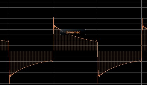
I´ve done some square testing on my preamp and it seems like something isn´t right. The squarewave is sloping.  In 100hz my wave looks like this.


If i scope the wave right after V2(before the 2x40kohms) it looks ok. If i scope it after the 35nF capacitor it looks like the picture above. In higher frequencies there´s no problem with sloping. Something to do with bass response?
 
Howdy parner!

And we have the same problem. And as we have different in/out-transformers and different (ef86/ef804) tubes the problem is elsewhere.
 

Latest posts

Back
Top