


Thee_Aldeen
Member
- Joined
- Jul 3, 2012
- Messages
- 16
stumbled over these pics on accident when i dug up an Post from '12 when i was trying to build a clone of the Sontec Eq.
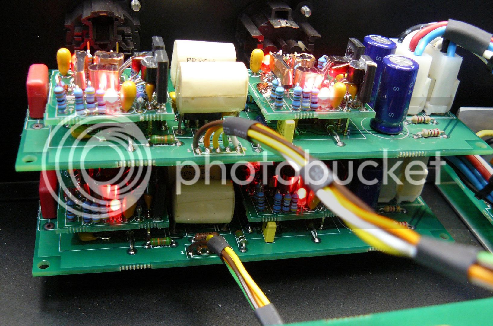
http://s251.photobucket.com/user/diy33609/media/P1020027.jpg.html
So there are (illuminated) LED's on these DOA's... now i just had my 1st expiernce w/ DOA's this month w/BA512's in the Hairball Lola kit i just finished & the (2) two DIY-990's i have extra to use at will ;D
My question is what DOA's are thee that have LED's on them, when i was going through my reasrch on discrete op-amps i did not come across ANY designs that had LED's ...and to be honest (YES! i like them STRICTLY for their eye-candy! I ADMIT IT OK!! lolz")
I have (2) two DIY-990's from hairball left over, i got (2) BA512's and (2) DIY-990's to see which i like better in my Lola, i have the BA512's in there now but have not been able to test my Lola yet as it is a 500-series module and i have to finish the enclosure & supplies for it (as i built my own & did not purchase a 500-series enclosure or lunchbox as the Lola is most likely the only 500-series i will own for the next 6-months).
If i were to buy another 500-series kit... it would be the MISSING-LINK-II for sure, that puppy i have read some gOoOood things about
any comments, advice, ideas, Pour-it-on Baby!! :")
best,
-thee
Pics of my builds mentioned about:
Hairball Audio Lola, 1176 Rev-A:
http://instagram.com/thee_aldeen/
...the REDD47 is next
using Mullard ef86 + HA100x ;D
...hope to hear some good ideas from you guys on what to use my extra DOA's for :") also any info on the magical Christmas-tree DOA's & where to find them :chuckles:
-ta
http://s251.photobucket.com/user/diy33609/media/P1020027.jpg.html
So there are (illuminated) LED's on these DOA's... now i just had my 1st expiernce w/ DOA's this month w/BA512's in the Hairball Lola kit i just finished & the (2) two DIY-990's i have extra to use at will ;D
My question is what DOA's are thee that have LED's on them, when i was going through my reasrch on discrete op-amps i did not come across ANY designs that had LED's ...and to be honest (YES! i like them STRICTLY for their eye-candy! I ADMIT IT OK!! lolz
I have (2) two DIY-990's from hairball left over, i got (2) BA512's and (2) DIY-990's to see which i like better in my Lola, i have the BA512's in there now but have not been able to test my Lola yet as it is a 500-series module and i have to finish the enclosure & supplies for it (as i built my own & did not purchase a 500-series enclosure or lunchbox as the Lola is most likely the only 500-series i will own for the next 6-months).
If i were to buy another 500-series kit... it would be the MISSING-LINK-II for sure, that puppy i have read some gOoOood things about
any comments, advice, ideas, Pour-it-on Baby!! :")
best,
-thee
Pics of my builds mentioned about:
Hairball Audio Lola, 1176 Rev-A:
http://instagram.com/thee_aldeen/
...the REDD47 is next
using Mullard ef86 + HA100x ;D
...hope to hear some good ideas from you guys on what to use my extra DOA's for :") also any info on the magical Christmas-tree DOA's & where to find them :chuckles:
-ta