Does my plan for grounding make sense?

GroupDIY Audio Forum

Help Support GroupDIY Audio Forum:

This site may earn a commission from merchant affiliate links, including eBay, Amazon, and others.

rotation

Well-known member
Joined
Jan 24, 2006
Messages
402
Location
slovenia
Hi!

I'm trying to make best grounding scheme for my two stage tube preamp (built p2p). When i first fired it up it hummed a little, so i decided to try another ground scheme. What i have in mind is this:
1. Soldering pin 1 on input to the chasis with very short cable.
2. Tie wires from the input trafo -, cathode, decoupling cap and the rest of the first tube's ground connections together.
3. Run this wire to the second stage and repeat the same thing there, so all minus poles of both stages are connected together.
3. Make my CENTRAL GROUND near last filtering cap of my B+ supply and connect there B+ minus pole, phantom minus and - pole from the last tube.
4. I will leave pin 1 of the output connector floating.
5. Ground pin from Euro connector will be soldered to chasis with very short wire.

Can anyone please comment my plan? I don't know if - pole from B+ needs to be connected to central ground and also to the - pole of my audio ground on amp? I guess it doesn't matter.

Regards from Miha
 
Hi rotation,

The two XLR's sound right.

The rest sounds like regular star ground so should work. WRT the B+ you need to link ALL grounds together.

Is the filament supply regulated? If not its best to reference it to about +50V. Just use a voltage divider from your B+ to ground to get the +50V. Put a 100uF or so cap across the bottom leg.

Make sure connect neither of the filament supplies (or their center tap!!) connects to ground.

Hope this helps

cheers
Nick
 
[quote author="nickt"]Hi rotation,

The two XLR's sound right.

The rest sounds like regular star ground so should work. WRT the B+ you need to link ALL grounds together.

Is the filament supply regulated? If not its best to reference it to about +50V. Just use a voltage divider from your B+ to ground to get the +50V. Put a 100uF or so cap across the bottom leg.

Make sure connect neither of the filament supplies (or their center tap!!) connects to ground.

Hope this helps

cheers
Nick[/quote]

Hi Nick, thanks for help.
So, my plan should work, ok. At the moment i'm reading those papers from Jensen about grounding transformer shields. It's interesting. I also found out that Germans included this connections in schematics, they are nice practical examples..
My heaters are regulated. Why do you suggest to reference them to 50V above ground if they are not regulated?

Miha
 
I think we are making the same "color" preamp.

I have a star at AC Mains ground.

I am running Center Tapped Full Wave with a 540V pwr xfmr to get 270V (with the usuall formula for rectification)

-The KEY here is that star and CT for HT goes to the Filter caps ground at one point.

Then Both tube stage Grounds go to Star. -I got this idea for Tracing the Tele V72 grounding.

-I made DC heater supply with a bridge and CRC section with the R Adjust on Test for the right Voltage.

No Hum, but I have some RF though that I am trying to fix.
 
[quote author="rotation"]My heaters are regulated. Why do you suggest to reference them to 50V above ground if they are not regulated?[/quote]

The Radiotron Handbook recommends it for lowest possible hum pickup from heaters - something to do with reverse biasing the filament to the grid or cathode (but I'm guessing). The real reason is that it works really well and I've done it before (albeit with guitar amps) :grin:
 
The heater is situated very close to the cathode and as such you can not run with a great potential difference between them as it will arc over. There is normally a maximum heater-to-cathode voltage stated in the datasheet.

I guess that this will normally be a problem if you are using a cathode follower output with a large bias voltage (i.e. cathode way above ground potential) to accommodate a large output swing. If you have a fairly conventional grounded cathode type of stage with just a few volts of bias I guess that it should be completely fine without an offset on the heater voltage.
 
> Why do you suggest to reference them to 50V above ground if they are not regulated?

There are -several- ways to get hum from heaters.

6V of (60Hz) Audio will leak into nearby 0.001V (music) Audio points. Balanced twisted correctly routed heater lines reduce this.

Even when the external wiring is balanced, there can be stray leakage in heater insulation. Not all tubes, but a few in every crate. If the cathode is well bypassed, a moderate positive voltage on both heater leads steers the leakage current away from the main audio path. You may not need it, until you change tubes. Since you can usually find a 10V-50V DC node (current should be quite small), it costs little to include it from the start.

These are two solutions to two -different- AC heat problems.

DC heat is another course. It must be CLEAN; slightly filtered high-ripple "DC" may be more annoying than simple 60Hz AC.

> you can not run with a great potential difference between them as it will arc over.

Right, except it is rarely a "fun" arc, the kind you post a video on YouTube. Most often, the amp works for a while, and then starts to sound like crap, and worse. You change the tube, all is well again, for a while. It just sorta fizzles.

Essentially all tubes are rated +/-100V heater-cathode. The customary DC heater bias is in the +50V range (not at all critical). 12AX7 and many tubes are rated +/-180V or 200V. 12AT7 is the major oddball, 100V; but I bet most were made with the same filaments and clay-dip as 200V types, somebody just didn't want to re-write the Registration Data Sheet. (Or needed a place to dump thin-clay heaters?)

It is a coat of alumina ceramic, like dinner-plate clay, so it should stand hundreds of volts, if perfect. Apparently production tubes were jolted with 500V to find defects. The early two-12AX7 op-amps idled one cathode at -200V; one Macintosh power amp had 12AX7 drivers with apparently +/-200V signal, and these are not notorious tube-killers. However some guys mis-bias the CF in 5F6-A guitar amps, hang the poor cathode up at +280V, it works for a while and goes to crap. So there is some function of time; and also obviously some difference between Golden Age US/Euro production and modern production.
 
[quote author="guavatone"]I think we are making the same "color" preamp.

I have a star at AC Mains ground.

I am running Center Tapped Full Wave with a 540V pwr xfmr to get 270V (with the usuall formula for rectification)

-The KEY here is that star and CT for HT goes to the Filter caps ground at one point.

Then Both tube stage Grounds go to Star. -I got this idea for Tracing the Tele V72 grounding.

-I made DC heater supply with a bridge and CRC section with the R Adjust on Test for the right Voltage.

No Hum, but I have some RF though that I am trying to fix.[/quote]

Hey, mine is "47 color" preamp. I don't know if you know it, this pre needs regulated HT to sound like original..
About the RF problem; i think Jensen is suggesting something like adding a few caps at the input to solve this problem. I'm not sure, read their paper about making mic splitters, RF thing (also a lot about proper grounding of tx shields) is well explained and there are practical examples too.
Btw, does bus grounding have the same efficiency as star grounding? I'm asking this because it is easier to run all grounds to one "- line" (like on schematic) instead taking every ground to central ground point. That usually means big mess with wiring...

Miha
 
Thanks Miha, I have the reg HT.

From my understanding, it is better for some of the components that are going to the tubes, be closer to the tubes. This would include Grid stoppers on V2 and any grid to ground resistors. So if you adhere to that the bus grounding should be fine, but beware of loops.

1. I had hum at one point due to the PRW XFMR center Tap connection point. though, I am not sure you are using CT to Ground?
-This should go to your Filter caps and then to Chassis(AC) Star.

2. You could try to hook up a 6V DC source to your Heaters to Rule out AC Heater Hum. A 6V Lantern Battery did the trick for me(Thanks to James Lee on that one).

3. Try to hard wire the Neg Feedback switch. Rather than running wires to the switch, pick a set gain setting and put the components closer the the main circuit. If that fixes it, then you will need better shielding on the wires for the gain switch.


Please describe your Power Supply grounding, I have a feeling that is the key.
 
Hi,
i had problems when preamp was not fully closed in chasis and grounding was not proper. So there could be more then one problem. That's why i first wanted to know if my plan is right.
At the moment i'm very occupied with event i'm doing, but when i'm done i will come back with the results.

Btw, my transformer doesn't have CT, it's custom made toroid with 220V and 12V secondary. And it's buzzing even when connected to fully working psu. Do you think i should return transformer like this?

About the grounding of psu;
HT plus goes where it have to go, minus goes to my central ground which is taken from the last filter cap (minus pole) of HT. Btw, my central ground is very close to the minus pole of last filter cap of HT..
Heater wires go directly to tube sockets and are not grounded.
I didn't use phantom for now, but my plan is to connect it directly to phantom resistors near input connector..

Yes, grid stoppers are soldered directly between tube pins. I use a mixture of bus and star grounding. The only thing that is quite far from tubes are anode resistors and decoupling. I was worried they could cause troubles, so i built the circuit this way before PRR told be they are not so problematic. I know it is better if decoupling caps are a close to tubes as possible..


Miha
 
That 220 may be a problem since 220x1.414=311V. Then CRC for Ripple is cutting it a bit close, especially if you take into account MAins variations.

Form my PSU, I went overboard with filtering, but I would think at least a 250V secondary on this amp. Maybe you are running HT unreg. Please provide more details. You can measure ripple to see if that's where your hum is.

It's unclear of your heater arrangement

I wonder if PRR would agree since he has much more experience.
 
Hum in a single ended tube amp is very common.

You can do things to reduce it if you feel that your recordings will suffer.

DC heaters, soldered ground instead of nuts and bolts for least resistance, you can move grid wires around a bit, add capacitance to the power supply, add a choke to the pwr supply, move the input and output jacks right next to each other so any outside ac does not induce hum thru the larger loop of wire.

Try connecting both pin 1 wires together.
 
Charlie;
i'm using Gyraf's psu for G9. Well, heater part is from Pultec (because i have 6,3V on tubes) and i changed feedback resistors from TL783 to get 290V that i need. I was not correct about transformer secondary, it's 230V and i get around 317V after the rectifier...
I think i found a problem with heater; it is not tied to ground. I will try what this means.
CJ;
Nice to see you back. Btw, hum is not very bad. When i tried preamp with a friend he said this is normal (we didn't meassure it). But since i never heard so much hum with good preamps i decided to do something about it.
XLRs are not close together because i didn't have space for output transformer. So now my output connections goes around 4 inches from transformer and psu board.

Thanks guys, i think i have enough informations now. I will build psu one more time (bad wiring after several experiments and fixes) and do some tests with scope too.

Mih

Miha
 
[quote author="rotation"]
I think i found a problem with heater; it is not tied to ground. I will try what this means.
[/quote]

From the Gyraf schem it looks like both HT and heater are grounded. Are saying both are not tied to ground? or, Are the cold heaters only connected to one side? That would be a problem.

What secondary rating do u have for heater AC?
 
I thought of you when I saw this

http://www.freewebs.com/valvewizard/heater.html


It seems you had questions about elevated filament setups.
 
Hey,
thanks for this, i didn't know it exists. Btw, i'm waiting for new TL783 regulator because mine died. This regs seem to be quite sensitive, so i might try to use Tubetec's HT partm of the psu. Check it here:
http://www.groupdiy.com/index.php?topic=29409&highlight=tubetec
I'm not saying TL783 is bad, but i want something more resistant for experiments. For example, when TL dies i get full rectified voltage to anode resistors. Not good.

Miha
 
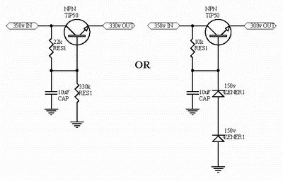
maybe try this

HVreg.gif
 
Hey,
i've seen this two regs before. Have you tried them? I'm asking because i need something variable, i guess it could be done by changing value of 10k and 22k resistors.
Btw, people are saying zeners are noisy. Can anyone explain me how noise enters into circuit if zener is not wired in series? And, can this noise be heard? I guess i could test this circuit with oscilosope and see what i get.

Regards from Miha
 
[quote author="rotation"]Hey,
i've seen this two regs before. Have you tried them? I'm asking because i need something variable, i guess it could be done by changing value of 10k and 22k resistors.
Btw, people are saying zeners are noisy. Can anyone explain me how noise enters into circuit if zener is not wired in series? And, can this noise be heard? I guess i could test this circuit with oscilosope and see what i get.

Regards from Miha[/quote]

No, changing the resistors only changes the current through the zeners.

To make it variable voltage you need to switch different value zener strings, but beware that voltage may surge as you do, and it's not a great idea. Shooting from the hip, I would suggest a variable Maida type regulator... take a look here http://www.national.com/an/LB/LB-47.pdf. Example here: http://giaime.altervista.org/maida.html.

Zener noise can be significant and the higher the zener voltage the worse they seem to be. In the example of the simple voltage stabiliser the noise enters via the transistor base, which after all is a gateway to the rest of the circuit.

For improved performance replace the feed resistor with a constant current source. Check the zener datasheet to understand their requirements. For the current source think IXYS 10M45, and don't forget that they need a 1000 Ohm gate stopper resistor. (http://ixdev.ixys.com/DataSheet/98704.pdf). Then put an RC filter between the zener and the transistor base.

Good luck.
 
Back
Top