scott2000
Well-known member
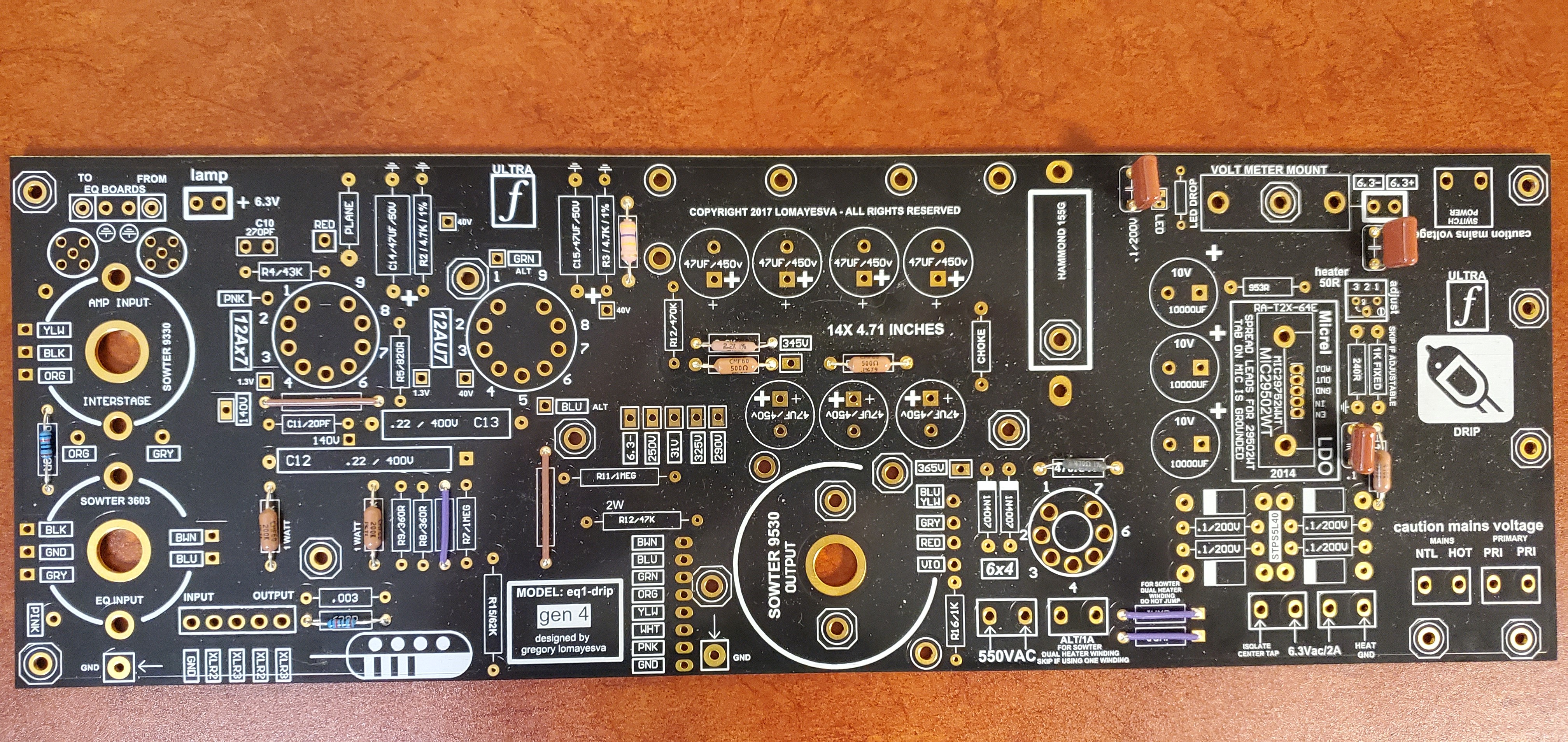
Vangetti said:I don't understand why on the PCB silkscreen has .1/220V capacitors in the 6.3 power section, but on the finished builds on drip's website, they're not there? Do you think I should put them in and test it out?
Just guessing without knowing where they connect but probably not necessary if they're just extra caps for the bridge......here's some discussion on this....
https://electronics.stackexchange.com/questions/14250/what-are-the-advantages-of-full-wave-bridge-rectifier-with-capacitors-parallel-t
Vangetti said:Also, would it be better to use the 6x4 rectifier tube instead of the 1N4007 diodes?
Shouldn't matter.... I guess that's subjective but it does the same thing....
Vangetti said:I ran into the same scenario. I would google the drip eq1 and found older documentation. The schematics that are uploaded on the drip website are the original Pultec schematics.
I was referring to this back panel guide....
attached PDF
Just in case .....
has to be something ....You'll figure it out.....