Dual compressor (Diode bridge + Vari Mu)

GroupDIY Audio Forum

Help Support GroupDIY Audio Forum:

This site may earn a commission from merchant affiliate links, including eBay, Amazon, and others.

Heikki

Well-known member
Joined
Jul 31, 2008
Messages
401
Location
Finland
I made a combination of my Diode bridge compressor and Vari Mu. This time I used 32 diodes in the diode bridge.

Schematic
Schematic for Vari Mu sidechain
Meter driver schematic

The meters indicate gain reduction done by the tubes and diode bridge gain reduction is indicated by a LED on the front panel (D69 & D72 on the schematic).

I used fixed time constants in the diode bridge sidechains and only threshold is adjustable. Vari Mu section has adjustable attack, release, ratio and threshold.


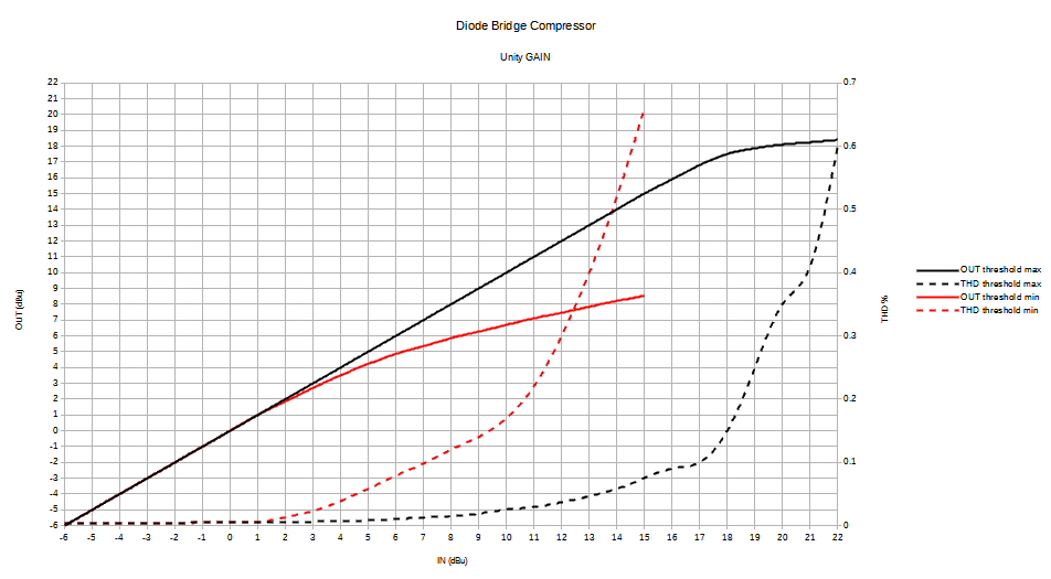
Compression curves and distortion when diode bridge compressor is used.
dualcompdiode.png

Compression curves for the Vari Mu section are basically identical to the curves I made for the Vari Mu compressor, so I didn't bother making new ones.
Vari Mu compression curves
 

Attachments

  • front.jpg
    front.jpg
    151.5 KB · Views: 98
  • inside.jpg
    inside.jpg
    239.3 KB · Views: 92
  • mainboard.jpg
    mainboard.jpg
    285 KB · Views: 80
So the limiter is on the diodes, compression on vari-mu?

EDIT: I see that the chip has tolerance to +/-80V, so you're most probably fine :) - in the system, you'll probably want to have protection diodes (inputs to -+15) on the input of the vari-mu-debalancing INA2134's (U12-13) to keep the input signal within its +/-15V rails - otherwise you could run the risk of frying it

/Jakob E.
 
Diode bridge compressor is marked as limiter on the front panel.

I’m not sure it would be a good idea to put protection diodes to voltage rails on U12 & U13 inputs. Common mode voltage swings can be larger than 15V on the inputs. The chip can handle these easily and I’m not exactly sure what the behavior would be like when the protection diodes would start drawing current as the common mode signal exceeds 15V.

Edit:I think the protection diodes would severely limit the INPUT COMMON-MODE VOLTAGE RANGE vs OUTPUT VOLTAGE.
 
Last edited:
I admire your work on this project, it looks really well made, & thought out. However, I would be interested to know the reasoning for combining both compressors in one box ? I think if I wanted to build a diode bridge & a vari mu compressor I would have done them in separate boxes. That way I could use them separately if I wanted, & therefore have a more versatile system.
 
The diode bridge compressor alone sounds great. Unobtrusive. I put it after the vari my first. But diode to shave off transients followed by varimu makes a lot of sense too. Maybe even more sense.

Am using pots for the diode comp for now until rotaries arrive.
 
Last edited:
INFO PLEASE...I do not understand what a diode bridge compressor is :-( I used A bridge to get negative gr voltage in a vari mu tube comp I built...is that all it means ? If not a basic theory would be helpful and appreciated.

Thx
 
Thx for the info. My variable mu uses a triode tap off input 6L7 to a 12at7 which is interstage transformed to the bridge for neg dc to feed to control grid of 6L7.....
So you could possibly tap output stage ac and go to a bridge for your neg dc control voltage... with time contents and level pot ???
Thx...sunny & hot in Oregon today. (for a change!!!!)
G
 
Very nice!

What software do you use to measure/plot the compression curves?
 
Hi Warpie
If you are asking gavin in Oregon. I do not use any software...i just used alligator clip wires to find the right RC constants for my particular case an then soldered in the best results. When I built this SE comp I lucked out...had a humming bastard on my hands til the obvious DC heater flaw was corrected. I can swap the GR 12at7 for a 12ax7 or 12au7 to change it too more or less aggressive compression...12at7 works best for vox and Channel patching duties.
G
 
Looked at the schematics in first post.

What does U3A do, hooked from between R21 and R22 to RefA and RefB? It's a feedback loop, no ? And as opposed to hooking the junction of R21 and R22 to ground ?
 
R21, R22 and U3A are there to keep the DC voltage at U1 outputs at the same potential as the junction of D10 and D11 / D42 and D43. That way the same current flows through the upper diode string and lower diode string.
 
I liked when both compressors are used together so I wanted both in one box.


I have couple extra PCBs for the diode bridge compressor. Send me a PM if you want to buy a set.

This combined topology (diode bridge + transformerless vari-mu) is such a cool idea. Would I be able to get a PCB for the combined version to build? Also, would it be possible to modify the GR relationships to create a see-saw effect between the two compressors, so that when the vari-mu clamps, the diodebridge is relaxed, but when the vari-mu starts to release, the diodebridge works a bit harder?
I've wanted a u73BT for awhile now specifically because of how i hear the midrange euphonic distortion appearing in between transient events. So it's like when drums and bass are out of the way, the harmonic distortion from the diode bridge becomes more noticeable and enhances the midrange content with some sparkle or fractal spray. I haven't heard this in any other compressor and it'd be amazing if your design(s) here could be modded to allow user control of clean <-> excessive artifacts from the diodebridge.
 
You could clamp the CV signal in the sidechain of the diode comp, so it lets very fast transients in the audio thru, effectively working on lower-level signals. I did that on the varimu standalone for sonic effect.

And on the other hand you could make attack and release super fast til it distorts.
 
Back
Top