Dynaudio BM6A RF interference [FIXED 100%]

GroupDIY Audio Forum

Help Support GroupDIY Audio Forum:

This site may earn a commission from merchant affiliate links, including eBay, Amazon, and others.

Kingston

Well-known member
Joined
Nov 1, 2005
Messages
3,731
Location
Helsinki, Finland
I have had these Dynaudio BM6A's for about 25 years. In our previous location they already suffered from RF interference if a phone happened to be close by in just the right angle. It was livable and I didn't bother trying to fix.

In our current location they both broadcast an equal amount of interference from something close by. The rest of the studio is completely silent and does not suffer from this. The speakers have the interference audible by equal amount whether cables are connected or not. The issue is clearly internal - and with both speakers behaving exactly the same - it's clearly a systemic issue.

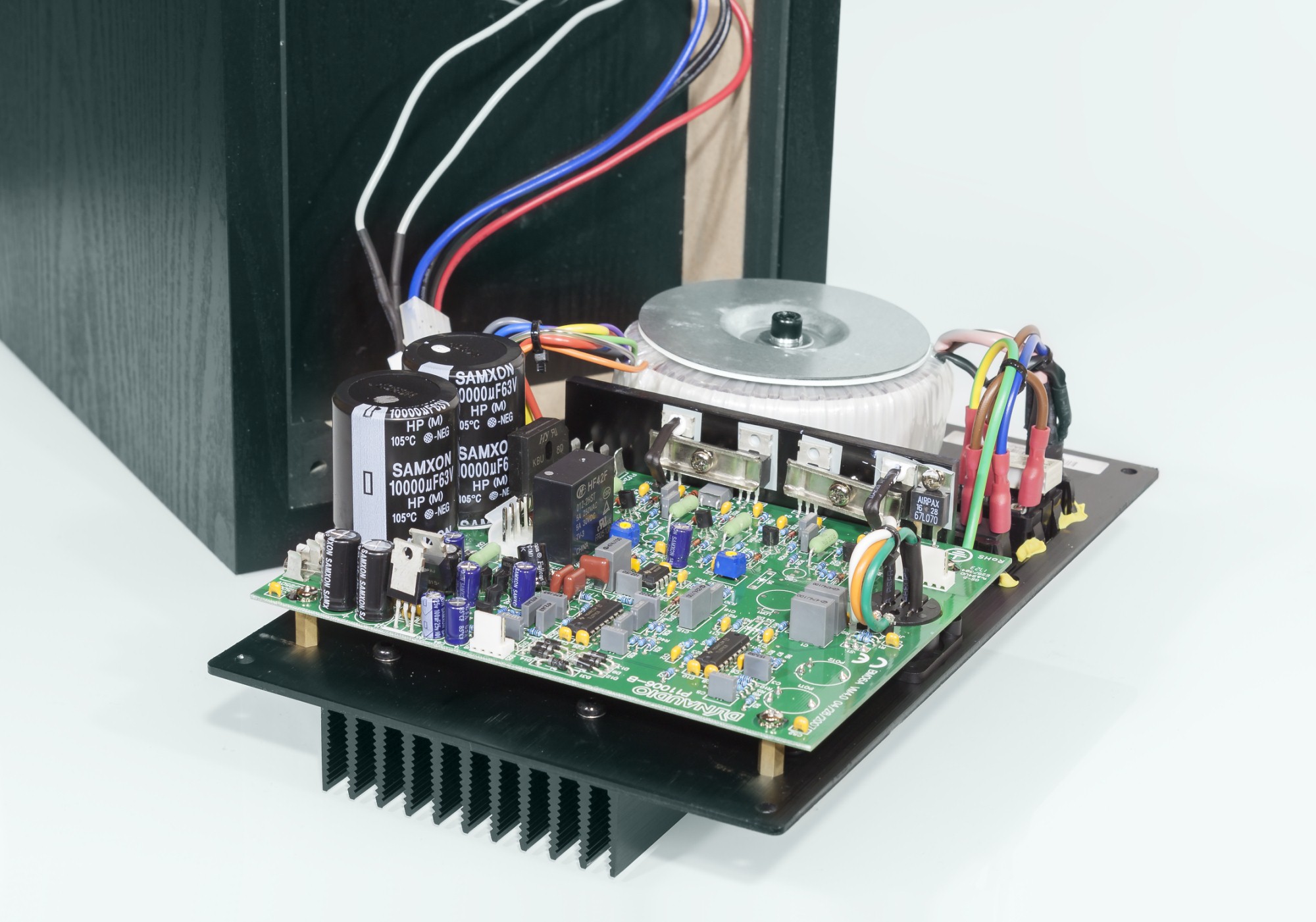
The circuits themselves are not protected by a faraday cage. They are just sitting on an aluminum plate. The electronics are exposed internally through the wooden structures of the speakers - the plate simply screwed on plain wood.

Would it help to try to fashion a proper faraday cage? I can fit one comfortably inside the unit and with connection to the already grounded metal plate I think it should work great.

Or what other sources of interference should I look for, if armed with an oscilloscope? Can the speakers themselves act as RFI receivers, and then there's nothing that can be done?

Schematic: https://groupdiy.com/threads/dynaudio-bm6a-amplifier-schematic.29065/#post-1087841
 
Last edited:
Now I attempted better protection. But the interference is still there. Unfortunately in this very quiet and optimized listening environment, still audible, even if barely.

Any ideas how to improve this on the schematic level? Anything to add to the circuit, better RFI filtering somewhere in there?

This is the oldest model MK1. I can see it doesn't have the rectifier diode parallel caps, and similarly does not have the mains protected by 100vF caps to ground. Can this help?
 
Last edited:
Try putting RFI chokes (clip-on ferrite cores) onto the cables first. Maybe you could try contacting Dynaudio, too, as they have CE marked the speakers, might be they already know the issue (another user complaints here: https://gearspace.com/board/studio-building-acoustics/1406193-nasty-emi-rfi-noise.html).

RFI chokes on the audio cables? But they are not connected. The noise is there whether I connect XLR cables to the rest of the system or not. Also I doubt Dynaudio will do much. These speakers are decades old.
 

That is precisely the same noise I hear, exact same frequency! Which I indeed made far more quiet with the faraday cage. Maybe I will just try a far more sturdy cage next, with much more professional materials.

Additionally, that's BM6A mk2 in the thread with the exact same issue, which saves me time installing those rectifier diode caps as they clearly don't help.
 
Last edited:
I know, but surely there's no wireless connection between the amplifier boards and the speaker deivers, is there? I know what i said ;)
Ahh of course! That sounds like a good idea. Any more specific recommendations for the clipons? Or of course I can solder out the cables and add non-clipons.

Although the frequency coming out from the speakers is not RF, but something that the amplifiers likely rectified to audible frequencies, so not sure if this will help...
 
Inputs seem to already have a RC filter (1k -> 150pF), wonder which part in circuit still works as an antenna? Also mk2 adds the 1nF caps in the input (XLR?). Could this be a pin 1 problem, why is there a 47 ohms resistor only?
 
Inputs seem to already have a RC filter (1k -> 150pF), wonder which part in circuit still works as an antenna? Also mk2 adds the 1nF caps in the input (XLR?). Could this be a pin 1 problem, why is there a 47 ohms resistor only?
The noise is there when pin1 is just dangling, when XLR is not connected. Does not make a difference if the cable is connected anywhere else.
 
What happens if you put ~ 100pF on pin1 to gnd/case?
Old equipment was not designed for wifi, 4G, 5G etc.
Would termination plugs on unused inputs work?
 
The noise is there when pin1 is just dangling, when XLR is not connected. Does not make a difference if the cable is connected anywhere else.
Your noise issue is almost certainly from nearby cellular transmission towers. This is becoming a very common problem in studios. There have been a number of threads on this topic here in the last year or so. If you do a search for "Neutrik EMC" you will find several of them, as the Neutrik EMC connectors can be a big help with this issue.
 
Before any more suggestions about cabling issues let's recap. This is the case design.

open-l.jpg


It's raw electronics dangling on wood. This was probably ok 30 years a go when it was designed. Without a proper cage, it's all just one big antenna, with multiple areas of the PCB subject to RFI.

I will try the pin 1 suggestions, but you are asking to stop RFI at a very specific point in this circuit, when it can enter the case literally anywhere it pleases.

My next attempt is 0.7mm aluminum, instead of kitchen grade crap. It's malleable enough that I can probably fit it both snugly, and without RFI entry points when connected to the heatsink backplate (and ground). Just to point out again: the kitchen grade crap already made a significant difference, but not perfect. Now I'll simply attack with an order of several magnitudes more thickness.
 
Last edited:
The thickness may not be as important as complete coverage.
The small yellow caps are likely 0.1uF thru hole having no effect on cell bands.
As the RFI is reduced with input terminated the input stage may be the most susceptible point. A 20 - 100 pF across the input should be tried. A series SMT inductor in the nH range should help.
 
I have the BM5A mk ii and it doesn't seem to have this issue. Maybe comparing them might reveal something?

You could also try shielded IEC power cables. Although unlikely the main cause of your issue, they can sometimes help.
 
The cables from the XLR to the PCB look like antennas to me. Replace them with as short as possible shielded cable with twisted wires inside the shield. Is the XLR connector made of plastics? That would mean it's full open to RFI which at 5G doesn't need that big hole to get through anyway. However, it might still be a must to shield the whole PCB area or the space where the PCB is located as the signal runs unbalanced via longish traces (vs. 5G wavelength anyway) on the PCB.
 
Last edited:
Back
Top