Elkatone 700

GroupDIY Audio Forum

Help Support GroupDIY Audio Forum:

This site may earn a commission from merchant affiliate links, including eBay, Amazon, and others.

dirtyhanfri

Well-known member
Joined
Jan 16, 2011
Messages
677
Location
Madrid - Spain
Hi

I'm fixing a Leslie-esque Elkatone 700 Amp

Here Is the Schematic


The problem right now is in the amp power supply (+/-40V) both polarities blow fuses as fast as I turn the power on. The rest of the amp seems to be working.

Having a look at the wiring, I found all the grounds are routed to the - lead of a 4700uF cap after the rectifier, and nowhere else. Only the IEC's earth is connected to the chassis

Should I route all that ground to the chassis? It's the first option I thought, and before touching anything it I'd like to be sure.

Any ideas or things to measure apart of that?

Thanks

EDIT: click on the schematic image for a decent size view
 
Yes, that fuses

Looking further the - side of the cap seems to be connected to chassis, It's a second connection under some wires.

I've found a burn resistor, R50, between the Audio output to the speakers and ground, 15 omhs 5W, I went to the shop for a replace and when I was back at home I found they gave me a 10r, it still blow fuses with it, but not with the amp card unplugged, no other resistor or caps looks damaged, I'm suspecting about the transistors. maybe I'll unsolder them and if it blow fuses that way
 
I just replaced the transistors T7 & T9, and put a 15 ohm resistor in R50 it's still blowing fuses.

I tried to run it without T7 & T9 and I got some burn resistors, R13 & R15, I'm thinking maybe C7 & C5 are died and shorting +/- supply to gnd?
 
I would first disconnect the supply load. See if it still blows fuses. Replacing stuff randomly just adds up costs. So start with just the supply.  You may have a failing bridge rectifier causing the fuses to pop.  So start with disconnecting the load and see what the power supply does. The fact it's both rails has me thinking it's in the PSU and the BR is a great place to start as it is right after the fuses
 
Without load, the +/- 40V. seems to work, reads about 51v in my voltmeter, as I turn it on with the amp card plugged in it blows.

Also I tried to turn it on without T7 &T9 it didn't blow the fuses but burn r13 & 15
 
51V without the amp board plugged is fine.  So we know the PSU is o.k. without the amp board.  I would test all the transistors.  Do you have a DMM?

Set your meter to the continuity / diode "bleep" test. Connect the red meter lead to the base of the transistor. Connect the black meter lead to the emitter. A good NPN transistor will read a junction drop voltage of between 0.45v and 0.9v. A good PNP transistor will read "OL". Leave the red meter lead on the base and move the black lead to the collector. The reading should be the same as the previous test. Reverse the meter leads in your hands and repeat the test.

Now connect the black meter lead to the base of the transistor. Connect the red meter lead to the emitter. A good PNP transistor will read a junction drop voltage of between 0.45v and 0.9v. A good NPN transistor will read "OL". Leave the black meter lead on the base and move the red lead to the collector. The reading should be the same as the previous test.

Finally place one meter lead on the collector, the other on the emitter. The meter should read "OL". Reverse your meter leads. The meter should read "OL". This is the same for both NPN and PNP transistors.

With the transistors on a pcb in circuit, you may not get an accurate reading, as other things in the circuit may affect it, so if you think a transistor is suspect from the readings you have got, remove it from the pcb and test it out of circuit, repeating the above procedure.
 
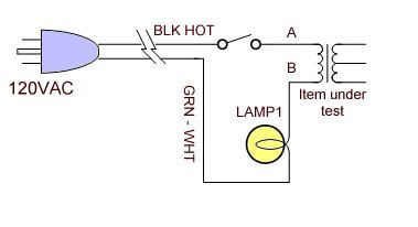
Use a 60-75w 230v lamp in serie with the mains to prevent more burned resistors, if you still have a short circuit the lamp will light up fully instead  ;)
A trick I learned in the 70's from a Peavey CS800 manual.
 
Tekay said:
Use a 60-75w 230v lamp in serie with the mains to prevent more burned resistors, if you still have a short circuit the lamp will light up fully instead  ;)
A trick I learned in the 70's from a Peavey CS800 manual.


The load lamp works great when fixing guitar amps too.
load_lamp1.jpg
 
Great, thanks for the tip, better than replace fuses every time I turn it on.

I measured the transistors, I couldn't get any OL in any lead position,  but they were installed on the board, I took out T5 and measured it alone, it was ok so I didn't take he rest out, I'll do it now.

The old T9 was faulty,  maybe it messed wih something else when wasn't working?

I replaced r 13 & 15, the burned resistors, and the four electrolitic caps (after 35 years I think it's time for a little recap). It was still blowing fuses, I tried to disconnect T7&9 and it burned another resistor (a 10r near T6).

T7 & T9 are TO-3 installed in a big heatsink assembled to the chassis. Maybe bad insulation was causing the short? They have some dry white glue under them (thermal paste?) And a thin plastic film (a bit broken actually). Collector is connected to the transistor chassis, and if it's shorting to ground through the heat sink it's a perfect suspect for a short right?
 
the white is thermal paste to keep it from over heating. The plastic is to keep it from shorting to the chassis. If the plastic is gone it will not working. If the paste is dried up, can always add more.
 
I'm trying the lamp trick and it lights, but not fully, just a bit, and I have +/-34V where supposed to have +/- 40, no burned resistors right now. Also, I'm trying without the heatsink, T7 & T9 sockets hanging in the air, I'll go shopping for thermal paste & new insulators.
 
Actually that was I doing

I lost the signal in T1 (md8002) in the B pin going to C4 & R4, I tried lifting the leg out of the pcb and there's no signal coming out of it, just a few milivolts of some kind of sawtooth  signal, independent of amplitude or freq of the incoming signal.

It looks discontinued, I'm not sure, but I have some mat-02 transistor around and I'm tempted to put one there and see what happens...
 
md8002? NTE makes a compatible part for that NTE81. Matches in their cross reference... I would use that first as it's available and usually a good drop in repalcement
 

Latest posts

Back
Top