1) Have you looked at the DIYAudio/Jan Didden Silent Switcher?
Yes. Not DIY friendly, uses difficult (Chipaggeddon) to get TI Chip's that are expensive. And the design is wholly unimaginative.
It would be trivial to do better:

Single Chip (U700) single inductor (below PCB, 6 X 6 X 4.5mm) with +/- 15V @ 0.3A continuous from a 3.7V/4,000mAh LiPo Battery, U703 is the battery charger/controller, output voltage is MCU adjustable from +/-6V to +/-15V continuously (PWM Pin), plus 5.2V from the Battery Charger IC when not charging.
There is also a -24V zener regulated, low current to bias J113 & J109 JFet audio switches and it would be trivial to add 48V and/or boost voltages.
All outputs are additionally LC filtered, switching frequency is 1.2MHz nominally and can be synchronised with an external clock, e.g. 1.411MHz or 1.536MHz or with the battery charger which cannot be synchronised externally.
The IC under the U700 label (Taiwan company made in china) is good for around 10W output from around 12W input power with 3.7V as source. More powerful options exist.
In principle, as long as the input voltage remains notably below the main +/- Rail voltages we can allow greater output power and higher output voltages are also possible if the input voltage is boosted.
So 12V would allow +/-24V @ 0.6A and with the next larger IC in the lineup we are looking at +/-24V @ 1.2A needing 12V/5A (continuous - so a 10A rated china adapter is recommended). At absolute maximum +/-48V @ 0.6A are possible, though that gets awfully close to absolute max stress values for all parts.
But I have no intent to produce something like this. Just too much hassle for little pay. I pay upfront to make 500, sell a few each month, even if I were to majorly gauge on the price it would not pay for my time just to pack this stuff and send it out.
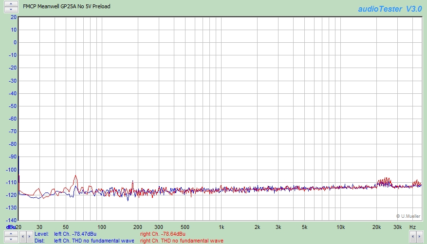
2) What's going on in the Meanwell GP25A?
Honestly, there are so many options to loblox up (as we say on planet anagramia) a simple switcher, never mind one with multiple outputs, that I'd have to analyse the the internal design in detail.
I prefer to talk about how I would go about things based on my experience delivering switching power systems for audio that don't have these problems.
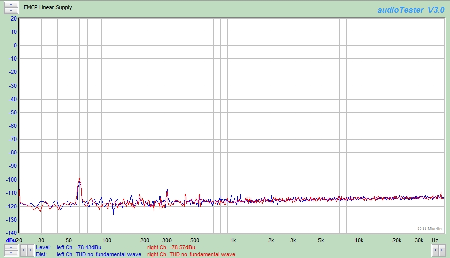
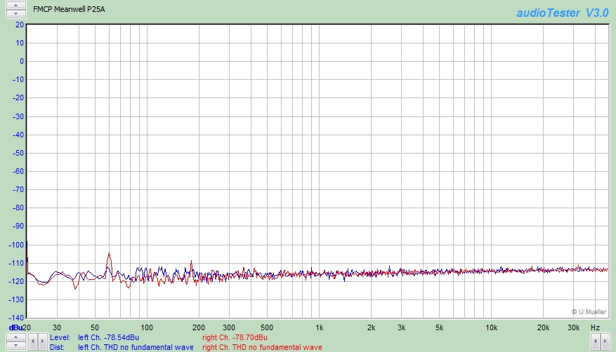
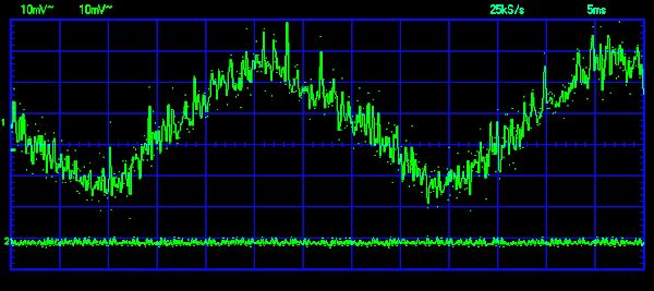
The original P25A didn't have this ripple: Meanwell applications engineers didn't seem to think the GP25A "green power" sample I had was defective.
They are only concerned if the unit meets factory spec, which I am pretty sure it does. Past that they don't give a hoot.
Thor