Fender tube tone stack for acoustic guitar (am I nuts!!?)

GroupDIY Audio Forum

Help Support GroupDIY Audio Forum:

This site may earn a commission from merchant affiliate links, including eBay, Amazon, and others.

Mondy

Well-known member
Joined
Feb 11, 2012
Messages
65
Location
UK
I play amplified acoustic guitar through a tube buffer and onto a regular mixer mic preamp and I really like the way the tube softens up the various pickups I use and helps reduce the harshness you can get when driving acoustic pickups hard as well as loving the "old school" vibe.  I wanted to take this further and develop a simple tube preamp to also get some gain and some basic EQ. To this end I strung a classic Fender 3-band tonestack between a couple of opamps set up to match the Fender tube source and load impedances to see what kind of sounds and EQ I could get, and despite everyone insisting that this type of tone control only being useful for electric guitars and overdrive, I managed to dial in some very useful sounds indeed for my acoustics

To keep things simple I thought why not try for a classic Fender electric guitar amp  style thing as I love that chimey bell like clean sound you can get with single coil electrics..

triode gain stage  >> tonestack  >> volume pot >> cathode follower >> transformer >> balanced out.

But as it is for acoustic, aim for minimum distortion (maybe a little 2nd harmonic to make it worthwhile using tubes) and the highest headroom I could get. So I started to design by Google, as my tube knowledge is practically non-existent, and try and sim some circuits in LTSpice to see what I can do. However so far success has eluded me. Either I get too much distortion or clipping or I get clean but not enough gain to compensate for the losses in the tone stack. I am hoping it is just me not knowing how to bias tubes correctly!!

My basic (essential) requirements are:
1. 1.0 Mohm input impedance (works best with the pickups I use)

2. High headroom (minimum signal capability around 1.0V Pk)

3. About 25dB first stage gain to overcome the tonestack loss and give a working final signal level.

4. Preferably use either 1x 12AX7 (too much gain?) or 1x 12AU7 (not enough gain?) as I have these to hand. I do not care about  the signal inversion as I can correct this on the output transformer wiring.

5. Lowest possible distortion from this type of circuit (with the tone circuit bypassed)

The closest I can get is from a pinched preamp circuit using a 6922 tube from here…

http://www.shine7.com/audio/6922_pre.htm

And plonking the tone stack in the middle of it like this…

https://sites.google.com/a/noratel.co.uk/ray/tube%20preamp.JPG

Seems to cover all the bases in sim land, but is this possible with 12AX7 or 12AU7 as I don’t want to shell out for a 6922 tube only to find the circuit (and possibly the whole idea) sucks!!?? With these two tubes I can try before I buy. Can any of you tube gurus give me some help here, is this possible or am I going to have to rethink?

 
A simple way to use the parts you have on hand is to use the 12AX7 but leave the cathode unbypassed. This will give excellent linearity and enough headroom, with gain around 31dB (using a 100k anode resistor).  Since this is 6dB more gain than you say you need, split the anode resistor into two parts (e.g. 47k+47k) and take the signal from the junction of the two. This  goes on to feed the tone stack and Bob's your mother's brother.
 
Hi,
my Rude Tube Ivory might be the thing you are looking for. In fact it's my approach to a fender champ preamp/tone stack . Very easy to build. Nice tube beginners project. You'll find it in Zayance White market thread.
Bernd
 
Thanks Bernd, you're right The Rude Tube Ivory looks right up my street. I have a feeling those power supply schems are just what the doctor ordered as well, It may be that I will have to fall back on your nice design!!

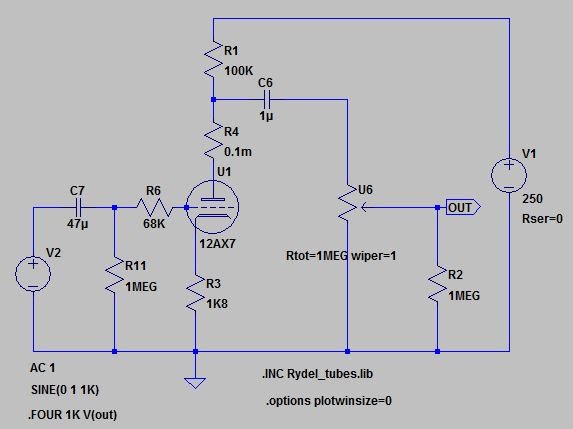
Merlin, I thought I would break the circuit down and sim each part before moving onto the next, so taking your sound advice (no pun!!)  I tried the following with the first half of the 12AX7 as my gain stage…

tube%20preamp%20V1.JPG


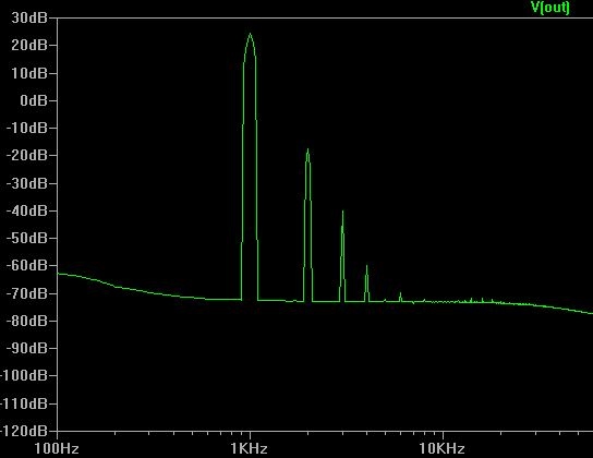
This seems to be giving me about 0.8% thd and an FFT below that looks a little too dirty (to my inexperienced eye!), I was hoping for mainly even order distortion and less odd as I want to keep the stage as clean as possible without going clinical (coz then I may as well go solid state)?

tube%20preamp%20V1%20FFT.JPG


Can the stage be altered or biased differently to improve this? I can sacrifice some gain as 25dB would be my minimum, but a little extra would be nice, or is this FFT perfectly acceptable for my needs?
Ray
 
For maximum headroom you need to set the bias point of the tube right in the middle, you can do this by adjusting R3, most likely it needs to come down a bit. You can also bypass R3 with a big value cap to increase gain. The classic fender clean tone is pretty well optimized, so why not start there and adjust to taste?

Look on the Aiken amps site for good information on tube operation.
 
> sim some circuits in LTSpice to see what I can do. However so far success has eluded me.

Have you tried actually *listening*?

Many thousand acoustics have been plugged into stock Fenders with happy results. Without checking with sims, without consulting a THD meter.

Distortion control in simple circuits is ALL about level control.

2nd harmonic rises in proportion to level. If you are offended by a 2nd harmonic reading, turn the level down.

3rd harmonic rises *faster* than signal level. OTOH, it also falls faster. So trimming your 2nd/3rd ratio is mostly about finding a happy balance.

Which means: plug into a Twin, adjust guitar volume and amplifier volume, until your ear is happy. You will typically want to push the preamp a little, until it is "colored", then leave the gitar knob set. With the amp volume semi-low, a 50W Twin will be very clean in the 5W-10W range. Turn-up, it gets a little more color when you lean into the pick. Turn way up, it honks 3rd harmonic when you emphasize notes and exceed 40-60W.

There are other problems finding the "Fender ring" with a good acoustic. E-gitars and their pickups have a severe top-cut. "Good" acoustics and their pickups should not be so high-shy. Fine through a clean system, but can get ugly fast through a bent system.

The Fender Twin preamp is also known as the Alembic. However the earliest ones drove high-impedance power ampifiers. Many plans you find will NOT drive modern power amps happily. Typically too much voltage and not enuff current. That's not a "preamp problem", that's an interfacing issue.
 
Thanks PRR!

Some very interesting reading! I have little experience with this as I have never owned a Fender tube amp of this type, only loving the clean sounds of the ones that I have heard!

Have you tried actually *listening*?

Yes of course, and a very good point. This is how I always do any solid state stuff as my knowledge of design is too limited to do anything else, but these experiments only need batteries to run.  This is why I first tried the tone stack strung between op-amps, setup to try and mimic the tube impedances and gains etc, so that I could listen while I fiddled and see if I could use the sounds available. I could!

But with tubes it is a little different as I have to make a suitable power supply which will take investment before I get the chance to listen. This is why I am trying to SIM as much as possible as well as ask for expert advice here on the Drawing Board.

John12ax7 is correct (thanks John!) the Fender first stage seems pretty much as good as I can get here. I scrapped the one tube idea as I couldn’t get it to work right and instead decided to go for both tubes that I have on hand. It turns out the tubes I have are in fact ECC83 and ECC82 and so I opted for ECC83 gain stages with an ECC82 cathode follower output.

So after a lot of Copy & Pasting SIM Trials have come up with the following schem which SEEMS to perform as I hoped…

tube%20preamp%202V.JPG


The output of the follower feeds into an OEP A262A3E wired backwards for 6.45:1 stepdown. Do you think this will run or is anything badly amiss, particularly the values around the Cathode follower (any part of the circuit really!)?

I am also wondering I f I need to elevate the heaters on the ECC82 (180V limit to Cathode?) or maybe drop the voltage to this stage a little?

Any help you can give me will be much appreciated!
 
> tried the tone stack strung between op-amps, setup to try and mimic the tube impedances and gains etc

The Fender tubes will swing 70V peak signal.

Opamps only 14V.

So gain-of-50 in the first stage works great with tubes, will overload on opamp.

You can bunt. Pick first stage gain as 10 (not 50) so the opamp does not overload. For an exact model you would add gain at the end to make-up the 5:1 you are short. However two gain-of-50 with a 10:1 tone-stack is about 5 times more gain than is needed to get from guitar to boxed power amp. (The full Fender has a low-gain power amp and often some mixing losses between.) The tube version probably needs some loss at the end, so there may be little or no need to add gain on the opamp model.

Your plan in reply #7 looks reasonable. R6 could be standard-value 33K. (Fender's 2*68K is non-critical.) You should have the option to add bypass caps at R3 R7 (you don't need the extra gain, but R3 R7 *linearize* the tube's bentness, and at lower strumming levels it may be near as clean as an opamp, but with extra hiss/hum).

You are correct that you are beating the heater-cathode rating. The plate of U2 (Fender 100K-12AX7-1.5K stage) will sit at 70% of the supply voltage. As you show 300V, this is 210V, plus a few for G-K bias. Also at turn-on the plate goes to full 300V, though the cathode won't follow all the way.

The WCF is a stunning thing when the mid-point sits at MID-supply. At best it is as clean as any opamp (so what is the point?).  Here it is forced to sit at 70% of supply, adding an odd non-Fender distortion overlay. Reducing B+ to the WCF would make this worse. Reducing B+ to the second stage gets you away from the classic Fender conditions in your Fender-based stages.

Also as I plot it out, this stage is flowing 22mA at 210V in U8 which is well past the 12AU7/ECC82 dissipation rating.

And a WCF with 22mA idle current and 60V peak swing can drive *1.5K* loads. Power amps (and mixers etc) are 10K loads. It's like 6 times hotter than it needs to be.

I'd take a new matchbook and sketch a small MOSFET cathode-follower with resistor loading. We may need 3V in 10K, 0.3mA peak output, so idle it at 2mA (plenty generous). Assuming U2 plate at 210V, the "cathode" (source) resistor can be 100K (1W!). The MOSFET design is using less current (no need to clean a whopping 22mA!) and has better PSRR than a tube WCF (could maybe be tapped one step dirtier on the power filter chain, leaving U1 and U2 on the cleanest tap with conventional 10K-22K and 32uFd-40uFd filtering). And no H-K breakdown troubles.
 

Latest posts

Back
Top