


CJ said:...lot of work on those 2 spreadsheets...
No credit for cross reference... I only did 1 sheet, the cross reference is something that came from a manufacturer I modified to keep track, there are several available, this is the best I found.
CJ said:...might want to add a Q category...compare the orig Pultec graphs...
Really? How to do that? The Q of the various Pultec sections that use inductors is influenced by the surrounding components and how each inductor was wound. For instance the high boost section (which is the only part of the EQP1 that uses an inductor) is influenced by a couple of pots and a cap and possibly the interstage transformer/inductance on the way out to the makeup gain. So really the useful comparison needs to be made "in situ" with that componentry replicated.
I can wind with any wire that will fit (as you know) and so I can get any DCR I want (subject to size constraints on low end).
At this point I am comparing core materials to look at saturation and BH loop to see what material AND core shape will replicate the distortion characteristics ( or lack of distortion characteristics ) of the Pultec inductor materials. I am looking for a NON toroid solution here, something I can wind on bobbins for as many channels as I want (It takes a LONG time time wind these toroids, and the taps break off because of my thumbs... It is not really DIY friendly and the auto winding machines for toroid use.. well I just can justify this expense to satisfy my curiosity about an analog process outmoded years ago)
From the "Pultec Inductors Again" thread http://www.groupdiy.com/index.php?topic=25482.msg516296#msg516296 we have a pretty good description of the core used to make an EQP1... You yourself posted dimensions
20 mm OD 14 mm ID 6 mm Height.
A L = 87
The cores I found on Nebraska Surplus are MPP cores from Magnetics (for less than a buck apiece!) and are (MPP which someone said is what Pultec used ... see attached datasheet, I think they might originally have been Arnold). They are 21 x 12 x 7 coated, and my measured AL varies from ... You later posted:
"Now we can get turns:
30 mH = 585 turns
50 mH = 756
80 mH = 956
100 mH = 1069
150 mH = 1308
So thats the way it was back then, there best audio band powder core could do 87.6
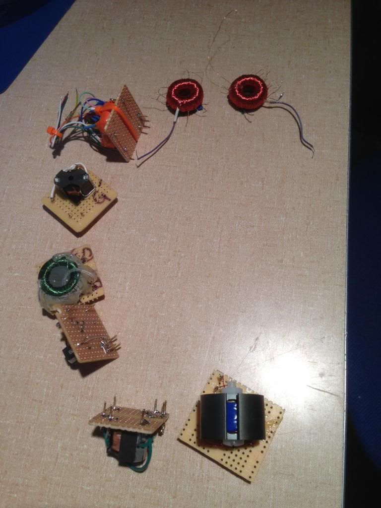
The Pultec inductor clones I wound come very close to these numbers... I will post a picture of them (I added some more taps because my clones included a Gyraf at first, before I got all historical <grin> ). The AL I measured ended up between 68 and 76 depending upon the actual core, but I have to say it is hard to lock in the actual turn counts when you are winding by hand (ADD folks... happy to wind forever, just don't ask us to count turns). But by my counts, adjusting AL as I wound I have:
34.9 mH = 716 turns
50 mH = 857
90 mH = 1050
100 mH = 1212
150 mH = 1485
(Re: your simulated Q suggestion I saw that you posted optimal Q frequencies for the various core permeabilities, but I don't really know how to measure or simulate the optimums.)
Here is the process I was thinking of following, let me know if you think there is a better faster (less winding) sort of way:
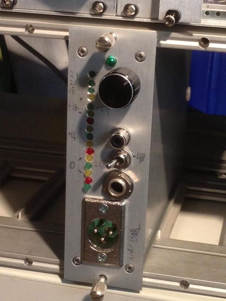
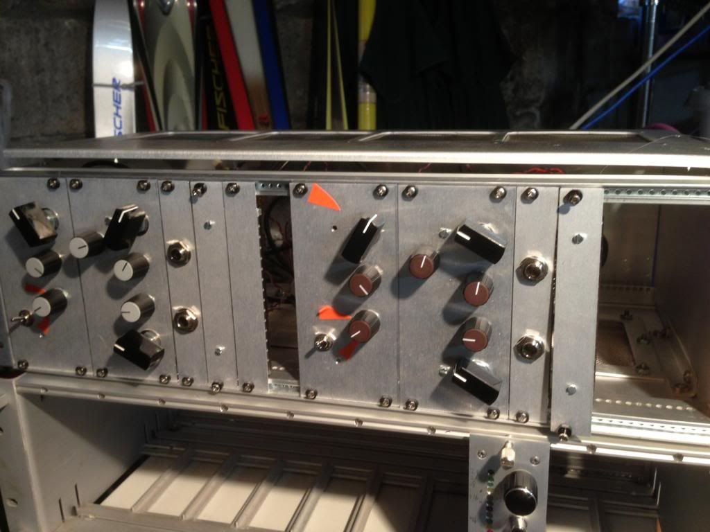
1) Build a (stereo) Pultec clone with modules so I can swap in and out various components. I did this in a Vector rack (I will post pictures). Solid state in and out boards of my own design to allow me to put whatever in and out trafo I want and not have the external equipment effect measurements as I change trafo's etc. Stereo lets me AB comparisons, and makes listening better.
2) Wound some inductors and tried them.
3) Using guidance from the above referenced thread, wind some close clone of the Pultec inductor. My best attept at this is using the above referenced core ( I can post measurements ) hand wound on a AL 70 ish MPP core using 34 gauge wire.
4) Measure that inductor for saturation characteristics ( would love to measure the BH loop but don't know how, only thing I can I think it is measured indirectly with THD ) which I did using the setup you suggested (I think I did that right). My setup is: Big driver amp - outputs to 51 ohm resistor - outputs to inductor tap - with the starting tap grounded. I put an oscilloscope across the inductor, and ran sine waves into it looking for the curve to deform (visually on the XT and also with XY display (BTW is that XY showing me BH loop?)). Is that test setup correct?
5) Make a spread sheet and hope CJ or some other brain surgeon comments (which he did, thanks very much!) to help me along in comparing.
6) Find core shapes and materials that COPY the characteristics of the Pultec toroid clone, but can be wound on Bobbins. I want to copy the saturation levels, and the BH loop, because both of these seem like the can effect the sound beyond the Q shape (which can be manipulated by winding differently). This is where I am now... still winding and testing....
BTW: I find I can not deform the curve above 1k Hz on pretty much any of these inductors across the 150uH tap below 11 volts RMS, levels I am pretty sure are never seen in the padded down world inside a Pultec. So I guess I am going to have to compare the inductors based upon the smaller taps, and below 1K, even though they are used above 1K (this makes me uncomfortable because the inductors are used at higher frequencies (but while I see how to do it, I cannot see the "Audio" relevance of the test method you described using a Variac, the levels are just too high and the frequency too low to be relevant inside a Pultec, I am already testing at 10X the max RMS levels seen in there, 100X seems overkill)
Early indications are that the practice over at Carnhill of using gapped cores (in the case of their RM7 cores... AL 400 ) is not far from what I come to using this test method. My test cores in the spreadsheet using N48 RM7's gapped to AL250 can take 2 volts plus at 20Hz well beyond what the Pultec toroid took.
Also... I get really weird shapes in the wave from some inductors when the saturate. Some saturate differently. They do effect the driving amp (which is why I put the 51 ohm resistor in to allow the core to distort before the amp so I could tell when it was the core and when it was the amp clipping. So far it is always the core except above 10V rms)


 sorry I'm bringing nothing to the table...


