fet boy

GroupDIY Audio Forum

Help Support GroupDIY Audio Forum:

This site may earn a commission from merchant affiliate links, including eBay, Amazon, and others.
alo
got the oep`s for the fetboy,and several questions come to mind:
does pin 9(ground tap?),needs to be soldered to the base plate?.
also:that same pin can touch the base plate?.
i seem to reminde someone tell that the can and the base plate,should be sanded(?) before soldering,so it would be easier to solder?.
i`m only missing the pad switch and the power tranny to power it up.
best regards
pedro
 
alo
got it.
saw meta-meta,in g9 ,and now it`s clear.pin 9 soldered to base plate,and base plate all around to the can,and lots of flux.
best regards
pedro
 
Hey Guys,

Here is my first one. I had to wire off board as I'm needing to get 2 into a 1U rack with a pair of Spectra Sonics 101's.

I'm powering off one of Peter C's Green Pre PSU's modded to put out a +24V rail.

FETboy3.jpg


And a sneak peek clip...

It is just a quick clip done on my Acoustic guitar with a Violet Black Knight, no EQ or processing, just a gentle Low Cut.

FETboy Acoustic Guitar 1.5MB (Updated 12/01/06)

I'm really enjoying it, a quick and easy pre to put together, and inexpensive.

I chose to use Tants in place of the recommended Polys for C2 and C4.

I compared it to another Forum members with the Polys and the Tants give it a 'darker and warmer' sound the Poly's have a clearer high end.

Cheers

Matt
 
alo matt
congrats.
i`m only missing the power tranny to finnish mine,because i ordered a wrong rating power tranny(2*12v)instead of a 2*24v.
best regards
pedro
 
alo
i`m building two fetboys,with a fabio`s psu.
what fuse rating should i use?
better:how can i know the value,instead of asking?.
best regards
pedro
 
alo matt
looking at your pic above,the label of the can of the tranny says the secondary is at the primary side.the primary is the side near the board edge;isn`t it?.please tell me so.
best regards
pedro
 
alo
today i fired up the fetboy and it smokes.
i can even see the legs of r5 making small bubles in the boards hole.
i tried what matt told regarding the tuning of the unit,but without the bd 135,the trimmers don`t change any value.
in the hamtone site,r5 it`s 1/2watt,and i put 1/4 watt.
help,please.
best regards
pedro
 
alo
thi is driving me crazy.
without the bd135 all it`s fine:as soon i put the bd135 r5 smokes.
there is one thing that puzzles me:why the* in the 47k resistor?
also the trim pot does not changes any voltages in the bd 135.
am i going dumb?
best regards
pedro
 
alo
i`ve been looking closely to matts fetboy,and a couple of things i`ve noticed:
no r4/r9,and it seems that q1/q5 have a component:which one?
i haven`t put anything in q1/q5.
best regards
pedro
 
Hey Pedro,

Sorry for taking so long to respond I've been on Holiday.

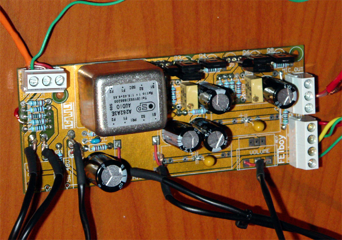
Don't worry about the sticker on my trano can, I stuck it on the wrong way round,
but the OEP can only go the RIGHT way onto the board, so don't panic.

You are right there is no R4/R9, because I'm using the trimmer. It is either
or, not both, that is prob why you are smoking stuff.

The idea was that R4/R9 47K was wired as a 'modest' guess for Biasing the
FETBoy but it is not very actuate hence the use of the 100K trimmer (BIAS / BIAS2).

There is an * next to R4/R9 which indicated to me that it might be optional
and looking at the original Hamptone design I saw this.

So remove the R4/R9, just have the trimmer in place and you should be fine.

Just check that nothing else smoked, but you should be up and running in no
time.

Also Q1/Q5 are the Jfets for the pre, it is not indicated in the BOM, but
you NEED these in order to have the pre work. The part I used from memory
was 2N5457 (I'll confirm this later).

But if you look at mine you will see I socked them, because you need to find
the best pair to work well together, as outlined in my set-up procedure in a
previous thread, which I'll post below:


----------
FETboy Fet Biasing procedure

1. Power up the pre without the fets (Q1/Q5)
2. Measure the V across R5
3. Adjust bias to have 4V across it (the trimmer)
4. Now put a fet in (Q1), don't solder it (I used sockets for my FET's)
5. Measure the V at the node before C2
6. Try all the fets you have and use the one that give you the nearest 12V
(Most of mine were around 14-15V)
7. If you get 12.3 or 11.7 just adjust bias to have 12V
8. Do the same for Q5 checking the V across R10 and the Node of C4

The other thing to do is to work out your HFE for the your Q2+Q3 and Q6+Q7 pairs.
The original uses a Darlington pair with an HFE of around 20,000! Fabio mimics
this with the BC550C's (I used BD139-16's). Try and match your HFE of those pairs
to give you close to, or over 20,000 HFE. Q2xQ3 = +- 20,000 HFE, and the same
for the other pair.

----------

I hope that helps you. Let me know ifyou need any more help.

Cheers

Matt
 
alo matt
the store i buy components doesn`t have 2n5457`s,so i`ll buy at another store,which will take a few days.damn.
best regards
pedro
 
Buy a whole lot!!!!!

I have bought 20 and one got 1 pair out of it suited for the FETboy! If you read my set-up procedure you will see you need to get some that measure around 12V, most of mine are 15V and had ones up to 18V.

Also check the set-up again, I've added stuff to it, I only mentioned checking one amp stage, you must check both.

Did you power it up without the resistors? No smoke?

Cheers

Matt
 
> Bauman, I'm getting the following message when I try to access your web page:
POR FAVOR, ENTRE EM CONTATO COM SUA EMPRESA DE HOSPEDAGEM.


I can't read that, but I see the URL ends in "/suspended.page/", which is a big hint.

If I strip off the end of the URL to find the top-page, I get what sure looks like a standard web-host company sales page, with "Setup Gratuito, Painel de Controle em Português, Suporte Técnico 24/7, 99.5% Uptime Guarante..." which has enough computer-english and common-Latin to guess "Free setup, control panel in Portuguese, 24/7 support...." And they have "Fantastico Scripts"! The word "Hospedagem" is prominent: I suspect "Web-hosting".

So they think his account is suspended. Maybe they didn't get his check. Maybe he exceeded the Gigabytes of the plan he paid for (they have plans at R$15/2GB, R$69/15GB, and R$490/80GB). Maybe he's fine and their computer is glitched.
 
Fabio is already informed about his website...he admitted he has to pay a small bill to the provider... :grin:
Should be OK soon, i think. :thumb:
(don't panic :green: )

Kind regards

Martin
 
What should be the voltage rating on the 10uf cap on the output?

Well if the Jfet's are biased correctly the voltage at the node before C2 and C4 (the 10uF caps) is 12V, so you should be more than fine will a 25 or 35V cap.

I used Tant caps not Poly's, I think in Poly they will start around 50V?

But basically anything above 25V is safe I would think.

Matt
 
Hey Matta, dont throw those "at not 12v dc out" away. Just change the
drain resistor to get 12 dc out. You get a little different gain but just
a few dB change.
Cheers Bo
 
Back
Top