FET DI design...

GroupDIY Audio Forum

Help Support GroupDIY Audio Forum:

This site may earn a commission from merchant affiliate links, including eBay, Amazon, and others.

SaMpLeGoD

Well-known member
Joined
Jul 19, 2007
Messages
441
Location
Portugal
Hello all,

I'm needing to do a pair of FET DI for my SSL9K preamp, and reach Igor's Fet DI and go between.
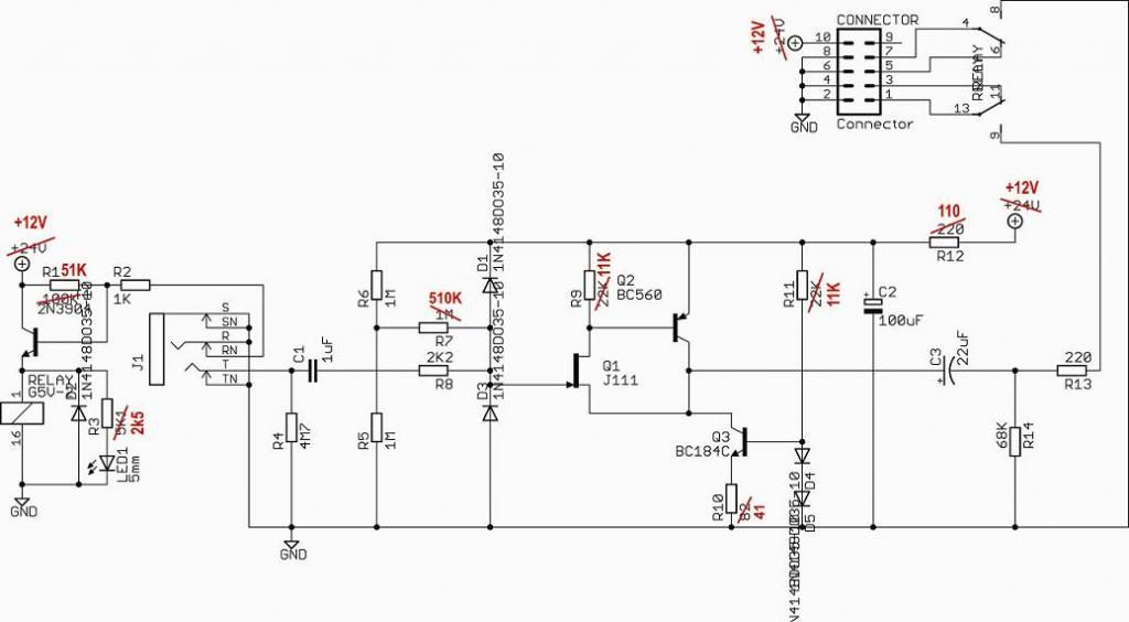
Since his FET DI are no long available on his store, I did into make one by myself, based on Igor's design... My problem is that his DI works with +24V and I need +12V... so I made some resistors changes and I appreciate that you comment this modifications and some issues about changing that.

FETDI12V.jpg


Thanks a lot!

Ed
 
You don't need to change every value to the half.
R1 value won't make much change... go with 51K or 56K that is easyer to find.
R3 leave it as 2K5 and make sure relay is 12V instead of 24V
R7 leave it at 1M, it's to bias the fet and could be higher but in this way you have >1M input Z wich is already good enoght for almost any electric instrument.
R10 should stay 82Ω as original, it's fixing the current at Q3 collector.
R11 is OK to be 11K as you put but easyer to find 10K and will work OK too.
R12 won't affect much, just for filtering, go with 110Ω or 220Ω

R9 should have better consideration, you could do 2 things, try if it works and see wich works better or wait someone with more knowldage on this kind of circuits put something here. I don't remember now good enoght about it, if nobody I can put something on it maybe tomorrow.

Take in consideration that you won't have as much headroom as in the 24V version, but it shouldn't be a problem.

AHH, wait... don't you have ±12V around... they are very similar to 24V! just use -12V as ground and change R4 and R14 to your new grounds.

JS
 
Hello Joaquins, thanks for the reply! nice explanation, thanks!

I was wondering... I think the best solution, talking about headroom and availability, is using the +48V rail.... what do you guys think about that... every preamp shoud have this rail, independent of the voltage that is used to it main's board... it's easy to find 24v relays, using a resistor to limit the current solve the relay problem working on +48V...
Any suggestions?
Cheers

Ed
 
you'll need a resistor and a cap, so the state voltage is lower than the 24 at the relay, may be 16V keeps it as it should, and during the initial transient is where it need heavier to turn on, so a cap in parallel with a resistor takes care of this...

Anyway 48V is a little too much, in the way I said you can use ±12VPS, ±15VPS won't make much difference, and +24VPS... with 51X you have two of this options already...

JS
 
R9 sets the current in the FET like id=0.6 V / R9
Since the FET is operated at a constant current, and most of the gm comes from Q2, this current has more impact on headroom / DC output offset than AC performance.

A follower like this might oscillate if loaded by a resonant circuit like an unterminated transmission line like a few meters of cable. If this happens it can be cured by bypassing R9 with a small cap to simulate a series inductor at high frequency.
 
VictorQ said:
R9 sets the current in the FET like id=0.6 V / R9
Since the FET is operated at a constant current, and most of the gm comes from Q2, this current has more impact on headroom / DC output offset than AC performance.

A follower like this might oscillate if loaded by a resonant circuit like an unterminated transmission line like a few meters of cable. If this happens it can be cured by bypassing R9 with a small cap to simulate a series inductor at high frequency.

R13 is to avoid/reduce oscillations but adding a zobel net at the out before c3 is better
 
ppa said:
VictorQ said:
R9 sets the current in the FET like id=0.6 V / R9
Since the FET is operated at a constant current, and most of the gm comes from Q2, this current has more impact on headroom / DC output offset than AC performance.

A follower like this might oscillate if loaded by a resonant circuit like an unterminated transmission line like a few meters of cable. If this happens it can be cured by bypassing R9 with a small cap to simulate a series inductor at high frequency.

R13 is to avoid/reduce oscillations but adding a zobel net at the out before c3 is better
Ahh right. I didn't notice R13. Stability probably won't be a problem, then..
 
Why are you using a 510K input resistor that makes no sense to me if you are going to build a circuit like the one shown a follower with an active constant current.
You have 510K in parallel with 4.7meg, even 1meg in parallel with 2.2meg is low for a jfet input.  What I mean is why use a jfet at under 1meg input resistance?

You can use a npn EF instead or a npn pnp pair or .. if you want under 510K input resistance

Why no cap to ground at the R5,R6,R7 node?

What input signal level will this follower "see"? 

If you change it to +- as joaquins posted you can also remove R5 and R6 and ground the side of R7 that was at the same node
 
Some of those resistor value tweaks seem arbitrary..  The operating current for the FET is established with a relatively PS voltage independent circuit. Dropping R11 in half will make almost no difference to the drop across the two diodes, while dropping R10 in half will double the current. Dropping R9 in half will double the current in the JFET before Q2 starts conducting and picks up the balance. R7 has absolutely no relationship to DC supply or operating current. Keep it high Z

12V seems marginal for hot signals but to maximize headroom with symmetrical clipping consider adding a trim in the bias string (or more PS voltage  8) ) and then adjust for most headroom.

JR
 

Latest posts

Back
Top