midwayfair
Well-known member
Good lord I did so many things wrong getting to this point. I probably learned more electronics planning this design than I had the rest of the last year at least.
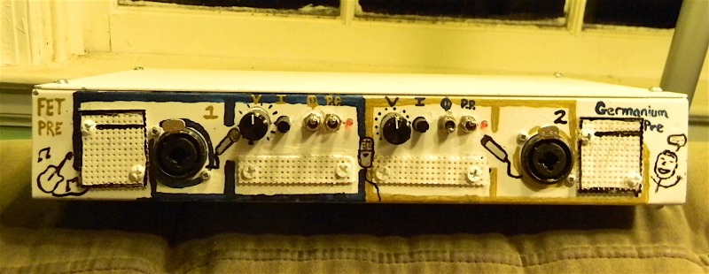
I'll get to the ... uh .... "unusual" enclosure elements later. (Hardly my prettiest work ...)


I have several neutral pres -- I wanted something with some color. These are doin' it for me. This was my first time building something with transformers, and my first time dealing with a high-current output stage using discrete parts, and I learned a lot.
I made a build document here (in progress and may need editing): https://docs.google.com/document/d/16242mJW2ZmwldvevZ6Yy1l5WBadvsuWd13oR7KGU258
Chances are this'll be shared on Oshpark as soon as I'm happy with the revised layout.
Here's a little bit about the design: It's a simple two-gain-stage preamp with buffering after each stage, using transformers to get some free gain (about 18dB in my build, but originally only intended to be ~12dB) and provide the balanced signal. Simple controls: The input pad is continuously variable down to -18dB, and it has phantom power, a polarity switch, and a volume/gain control. The FET side is a voltage divider in between the gain stages; the Ge side is simply one high gain stage (the Ge transistor) with a negative feedback control (on the emitter bypass cap, not coming after the second gain stage) providing 1x to 70x gain going into a low-gain stage followed by the output buffer. They have similar total levels of gain (~62dB with the output wired 1:2).
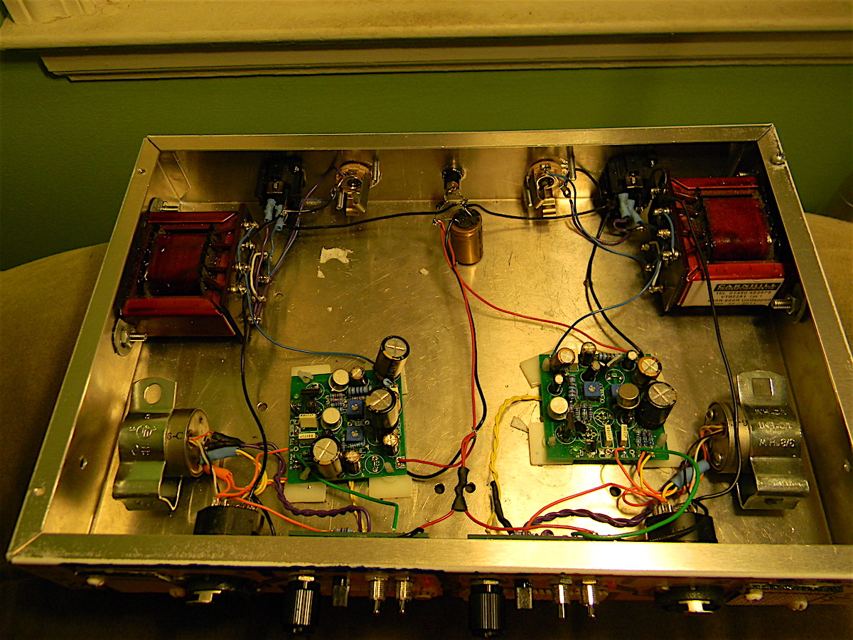
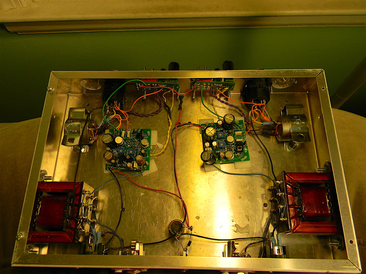
Transformers are Jensen 13k6 for the input and Carnhill 2281 for the output. Big thanks to KMB-AUDIO for the Carnhills! The Jensens were harvested by Dave Rox (in Elkridge) from an NPR console.
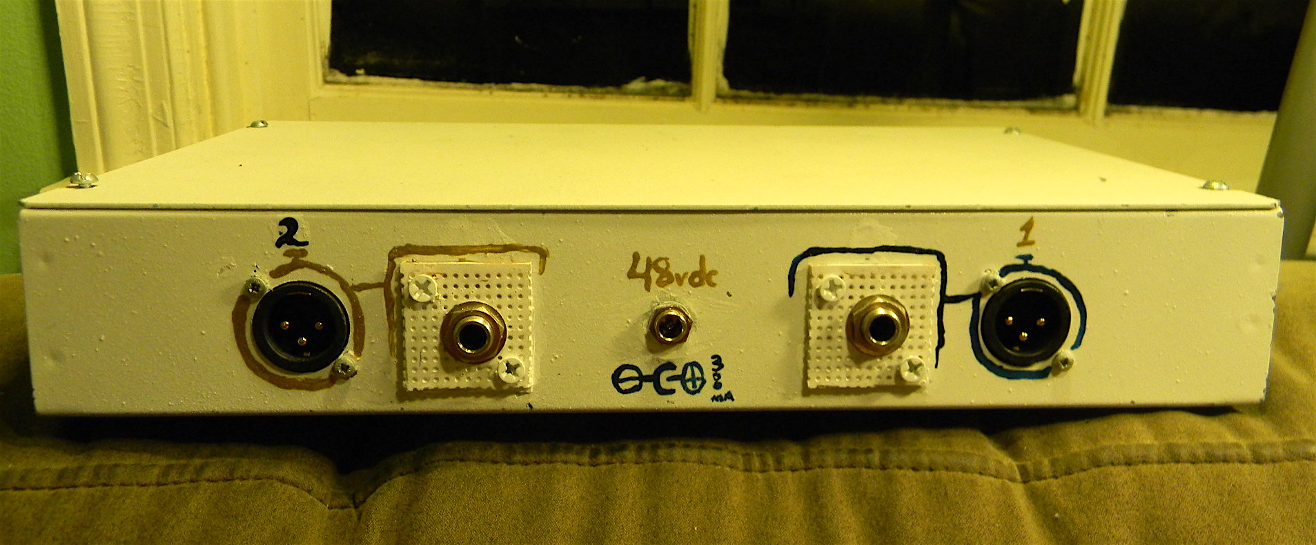
If you're wondering "where's the power supply?", the whole thing runs on a single 48V adapter I got on Ebay for $10. It can probably power eight of these. The phantom power is taken directly from the power supply, and then the preamp can be run on whatever voltage you want to regulate it down to. The Ge is running on 24V (which is plenty) and the FET side is running on the 48V.
There is potential for add-ons. I am pondering an optional/alternate control panel that adds a basic passive EQ section, and there is also a way to introduce FET compression like how my Bearhug (guitar pedal compressor) works, though it needs a significant revision to handle the gain level of the preamp. I just tried to make the preamp board itself as basic as possible.
I like both sides. They are different and each has its use. The Ge side is surprisingly quiet -- it might actually be quieter than the FET side, which surprised me, but I do remember seeing a post from PRR that Ge transistors are actually very good at handling low impedance signals and that their hiss problems tend to come about with higher impedance sources. The Ge side sounds slightly richer. The FET side has a nice "sheen" and less headroom.
All right now for the "comedy of errors" part. Here are the problems I ran into:
1) I adapted this from the FETboy/Hamptone FET preamp project, which uses an extremely high-current buffer after each gain stage. Unfortunately, the original project may have relied on some older, low-gain transistors for the stage, and offered to way to consistently control the current. PRR, Jack Orman, and several others on DIYSB were a huge help in getting the output stage to work right (using an LED + 1N4001 to provide a control voltage), but not before I destroyed several transistors and a lot of (even 2-watt) resistors caught fire. I literally couldn't have gotten this project to work without their help, because I couldn't figure out what was going on in the FETboy's output stage. The control voltage solved the problem perfectly.
2) I made a couple mistakes on my schematic and left off a couple parts and missized a couple others. If you see a couple of the big electros look "unsteady" -- that's why. I forgot the minimum resistor for the gain pot, so I had to finagle that on the control panel PCB. The power darlington for the voltage regulator had the wrong pinout for the spec'ed part. Plenty of uglyness here, and I almost scrapped the PCBs to order the fixed ones, but it's no worse for me than working on perfboard, I figure.
3) I did not understand that microphone input transformers had to be enclosed and shielded with mu-metal. So when I first fired this up, I was using open frame transformers (from Edcor) and getting extremely loud 60-cycle hum radiating from basically every electronics device in my house. It probably took me an entire weekend to finally fully identify the problem -- all the more frustrating because I hadn't done my testing on the breadboard properly. Some folks on this forum helped me out with that issue, and CJ even wound me custom transformers that are going to be used in my next build. Fortunately, the Jensens I got from Dave Rox make it as quiet as can be (at least for me).
4) Related to that, I was getting a ton of crosstalk. Originally this was supposed to be a 4-channel project, but I ordered the wrong width enclosure (I got 12" when I needed something more like 16"), and I was at one point able to plug a mic into channel 1 and hear it through the output of Channel 2! So I had to rip out two of the channels and figure out a clever way to cover the holes in the chassis. I used perfboard, drilled/filed holes in it, and then screwed it to the enclosure and painted it white. You can also still see some sticky tape on the floor of the enclosure. It does kind of bother me ... all that extra space in there ...
5) Finally, I ordered jills instead of jacks for the rear panel. Leevibe rescued my dumb ass and hooked me up with some XLR males. That was the last thing I needed to button up the project before using it on Saturday for a recording session!
Since I used it on a recording session, I'll eventually have clips. I didn't distress it too much. I ran an RE20 into the FET side and my ribbon mic into the germanium side on a stereo amp setup, and there were two other microphones involved in the session.
The D251 build I recently completed (thanks to Christopher L for the emporium deal ... he did most of that build) works well through the FET side on pretty much any source but needs the pad in for louder signals through the Ge side.
I'll get to the ... uh .... "unusual" enclosure elements later. (Hardly my prettiest work ...)


I have several neutral pres -- I wanted something with some color. These are doin' it for me. This was my first time building something with transformers, and my first time dealing with a high-current output stage using discrete parts, and I learned a lot.
I made a build document here (in progress and may need editing): https://docs.google.com/document/d/16242mJW2ZmwldvevZ6Yy1l5WBadvsuWd13oR7KGU258
Chances are this'll be shared on Oshpark as soon as I'm happy with the revised layout.
Here's a little bit about the design: It's a simple two-gain-stage preamp with buffering after each stage, using transformers to get some free gain (about 18dB in my build, but originally only intended to be ~12dB) and provide the balanced signal. Simple controls: The input pad is continuously variable down to -18dB, and it has phantom power, a polarity switch, and a volume/gain control. The FET side is a voltage divider in between the gain stages; the Ge side is simply one high gain stage (the Ge transistor) with a negative feedback control (on the emitter bypass cap, not coming after the second gain stage) providing 1x to 70x gain going into a low-gain stage followed by the output buffer. They have similar total levels of gain (~62dB with the output wired 1:2).
Transformers are Jensen 13k6 for the input and Carnhill 2281 for the output. Big thanks to KMB-AUDIO for the Carnhills! The Jensens were harvested by Dave Rox (in Elkridge) from an NPR console.
If you're wondering "where's the power supply?", the whole thing runs on a single 48V adapter I got on Ebay for $10. It can probably power eight of these. The phantom power is taken directly from the power supply, and then the preamp can be run on whatever voltage you want to regulate it down to. The Ge is running on 24V (which is plenty) and the FET side is running on the 48V.
There is potential for add-ons. I am pondering an optional/alternate control panel that adds a basic passive EQ section, and there is also a way to introduce FET compression like how my Bearhug (guitar pedal compressor) works, though it needs a significant revision to handle the gain level of the preamp. I just tried to make the preamp board itself as basic as possible.
I like both sides. They are different and each has its use. The Ge side is surprisingly quiet -- it might actually be quieter than the FET side, which surprised me, but I do remember seeing a post from PRR that Ge transistors are actually very good at handling low impedance signals and that their hiss problems tend to come about with higher impedance sources. The Ge side sounds slightly richer. The FET side has a nice "sheen" and less headroom.
All right now for the "comedy of errors" part. Here are the problems I ran into:
1) I adapted this from the FETboy/Hamptone FET preamp project, which uses an extremely high-current buffer after each gain stage. Unfortunately, the original project may have relied on some older, low-gain transistors for the stage, and offered to way to consistently control the current. PRR, Jack Orman, and several others on DIYSB were a huge help in getting the output stage to work right (using an LED + 1N4001 to provide a control voltage), but not before I destroyed several transistors and a lot of (even 2-watt) resistors caught fire. I literally couldn't have gotten this project to work without their help, because I couldn't figure out what was going on in the FETboy's output stage. The control voltage solved the problem perfectly.
2) I made a couple mistakes on my schematic and left off a couple parts and missized a couple others. If you see a couple of the big electros look "unsteady" -- that's why. I forgot the minimum resistor for the gain pot, so I had to finagle that on the control panel PCB. The power darlington for the voltage regulator had the wrong pinout for the spec'ed part. Plenty of uglyness here, and I almost scrapped the PCBs to order the fixed ones, but it's no worse for me than working on perfboard, I figure.
3) I did not understand that microphone input transformers had to be enclosed and shielded with mu-metal. So when I first fired this up, I was using open frame transformers (from Edcor) and getting extremely loud 60-cycle hum radiating from basically every electronics device in my house. It probably took me an entire weekend to finally fully identify the problem -- all the more frustrating because I hadn't done my testing on the breadboard properly. Some folks on this forum helped me out with that issue, and CJ even wound me custom transformers that are going to be used in my next build. Fortunately, the Jensens I got from Dave Rox make it as quiet as can be (at least for me).
4) Related to that, I was getting a ton of crosstalk. Originally this was supposed to be a 4-channel project, but I ordered the wrong width enclosure (I got 12" when I needed something more like 16"), and I was at one point able to plug a mic into channel 1 and hear it through the output of Channel 2! So I had to rip out two of the channels and figure out a clever way to cover the holes in the chassis. I used perfboard, drilled/filed holes in it, and then screwed it to the enclosure and painted it white. You can also still see some sticky tape on the floor of the enclosure. It does kind of bother me ... all that extra space in there ...
5) Finally, I ordered jills instead of jacks for the rear panel. Leevibe rescued my dumb ass and hooked me up with some XLR males. That was the last thing I needed to button up the project before using it on Saturday for a recording session!
Since I used it on a recording session, I'll eventually have clips. I didn't distress it too much. I ran an RE20 into the FET side and my ribbon mic into the germanium side on a stereo amp setup, and there were two other microphones involved in the session.
The D251 build I recently completed (thanks to Christopher L for the emporium deal ... he did most of that build) works well through the FET side on pretty much any source but needs the pad in for louder signals through the Ge side.


