


seavote
Well-known member
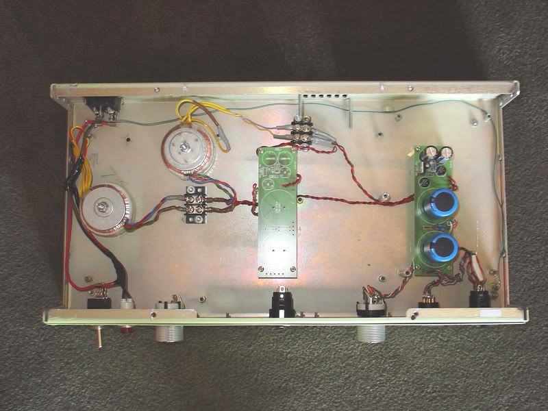
my past threads about my g7 are long and have solved some problems so im starting fresh with this one. this problem has me stumped for a while. i'm using gustavs pcb's. my psu is going to be a dual psu one side for my G7 the other for a royer mod. here is a photo:
The problem presents itself with or without the mic plugged in. with the mic attached im getting ther correct voltages out of the psu and in the mic circuit itself, everything seems fine. when the 3 pin xlr (audio out) is connected to either of my 2 preamps voltages read fine. when i plug the preamp out to my pcs' break out box the B+ voltage drops from 170V to about 110V.??? since i had fried my psu circuit due to an ac outlet that was wired incorrectly and much of it was wired point to point i decided to populate a new psu pcb (and a new mic pcb while i was at it, i purchased enough of everything to make 2 when i first ordered)to see if the problem was located on the pcb boards. both the mic and psu are neatly and cleanly put together.
my break out box is an M-Audio delta series break out box with 1/4 balanced inputs. the only components that are the same are the ac inlet,power switch, the indicator light(which i connected in parallel across the + and - ac wired as i had seen in some guitar amp schematics) and the transformers. where should i be testing next. i'll be getting a new xlr to 1/4 balanced cable and checking that although the cable tested ok with my dmm. please help im real close to getting this up and running. i've got parts for other projects waiting patiently but i wont start them till this is up and running. thanks