


barthman.de
Well-known member
Sorry this should not be a poll - I've only a question :")
I've a question to the G9 circuit diagram. It shows the following output transformer part:
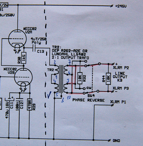
The output transformator ought to be wired 2:1. To get 2:1 I think the secondary of the transformer must be wired as follows: connect Pins 6 to PIN 9; (+)"hot" to PIN 7; (-)cold to PIN 10.
In the circuit above I think the output is wired only to one winding of the secondary. Why that? 2+2:1=4:1 not 2:1 ?!
At the layout of the printed circuit board (look at http://www.barthman.de/bilder/g9_pcbs.pdf) the output transformer is not wired as shown in the circuid diagram isn't it?
The second question I have is: How must be wired R32 and R44?
I drawed the following circuid from the printed circuit board:
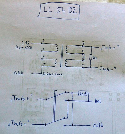
Is this connection of R32 and R34 right?
Why two of this 10k resistors? Would not be adequate one 10 k resistor to load the transformer?
I've a question to the G9 circuit diagram. It shows the following output transformer part:
The output transformator ought to be wired 2:1. To get 2:1 I think the secondary of the transformer must be wired as follows: connect Pins 6 to PIN 9; (+)"hot" to PIN 7; (-)cold to PIN 10.
In the circuit above I think the output is wired only to one winding of the secondary. Why that? 2+2:1=4:1 not 2:1 ?!
At the layout of the printed circuit board (look at http://www.barthman.de/bilder/g9_pcbs.pdf) the output transformer is not wired as shown in the circuid diagram isn't it?
The second question I have is: How must be wired R32 and R44?
I drawed the following circuid from the printed circuit board:
Is this connection of R32 and R34 right?
Why two of this 10k resistors? Would not be adequate one 10 k resistor to load the transformer?