


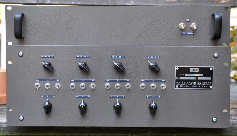
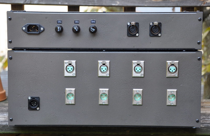
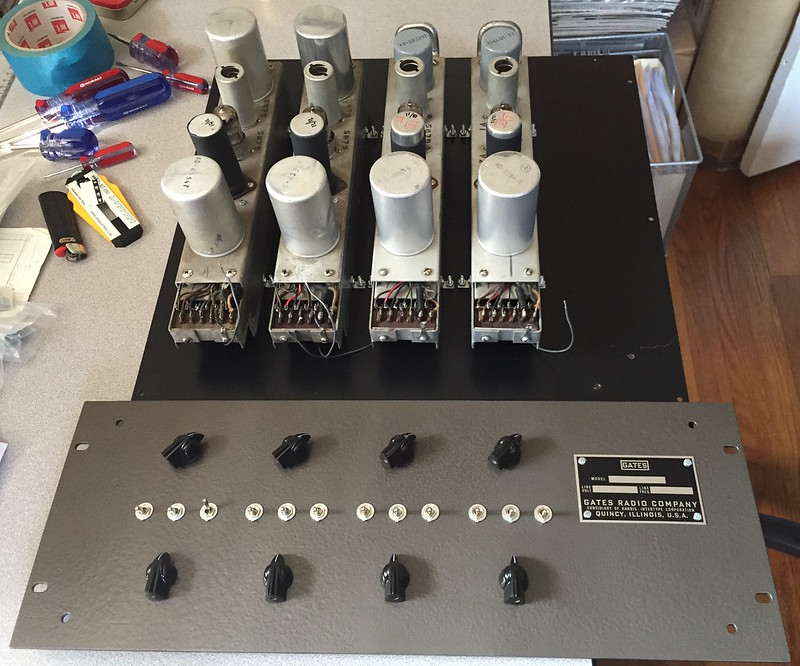
Here's a process log on a restoration and rack-up I apparently never posted. These were for a client, he had the amp modules already and sent them to me. He wanted all the modern conveniences, along with padding for line use, so the input pad is -20/30/40. These are fixed gain as stock, I sorted out +/-6dB feedback modifications on rotary switch positions. Unobtainium mating connectors with these, so had to solder directly. I found a real Gates logo for the front panel. PSU's are all DC and off-the-shelf. Linear B+ and filament, switching 48V.
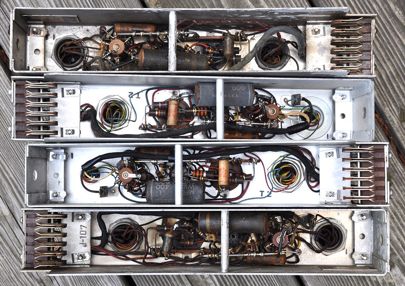
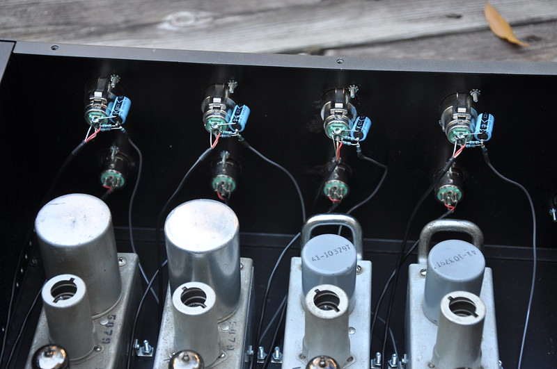
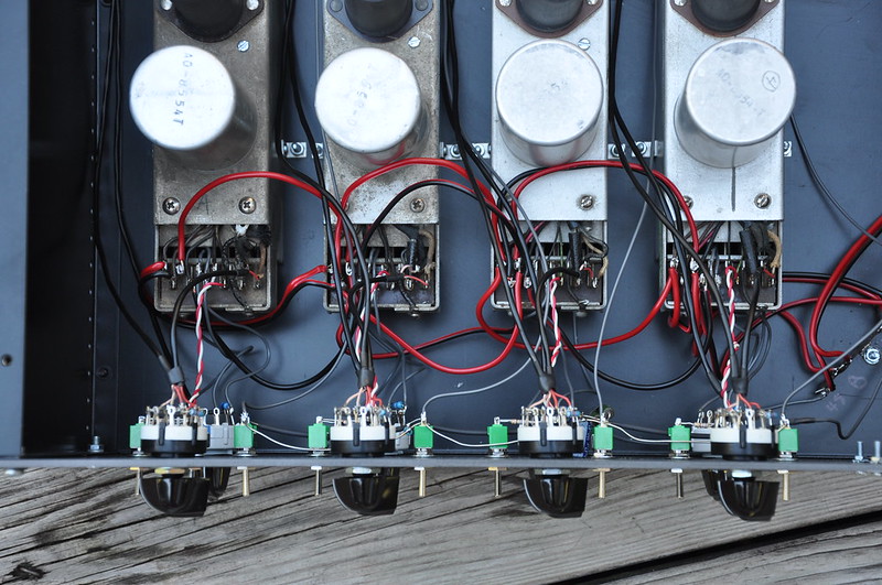
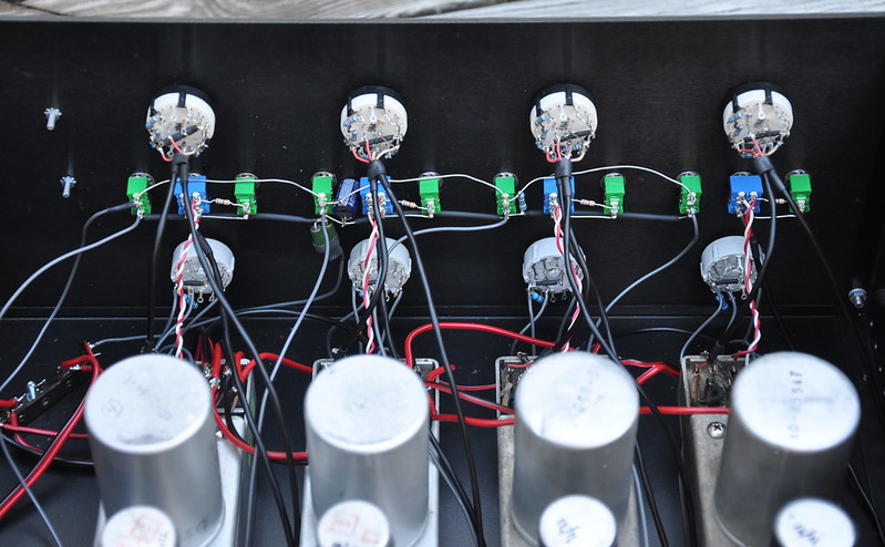
The can cap replacement/re-stuff was a serious pain due to use of point to point construction and Vector sockets, very little room to move in there. Fourth picture shows the deal. Here’s a separate thread on that.
How to: restuff an electrolytic can capacitor is where the above link is NOW - forum formatting changes have shit-canned old internal links like this! Have fun finding anything!
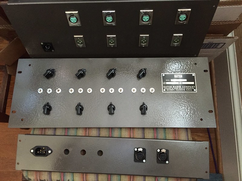
I took this pic before the clear coat was totally dry on the labels, so they look a bit milky.
Click this link for larger pic
Click this link for larger pic
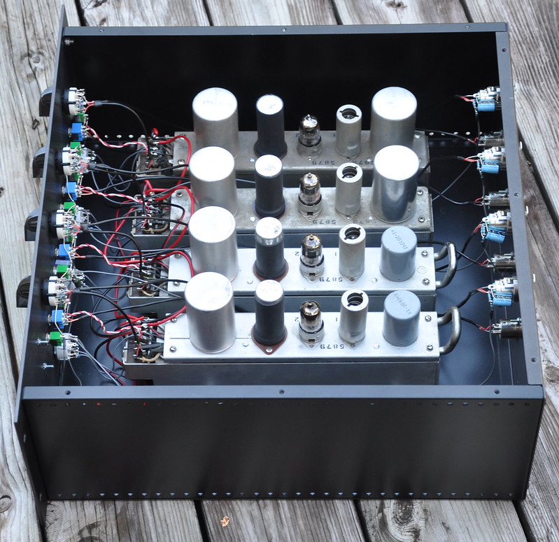
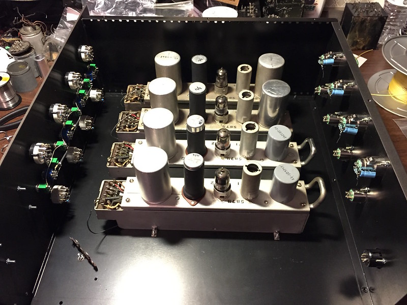
Wiring has enough extra length to lay front and rear panels down flat for service.
Click this link for larger pic
Click this link for larger pic
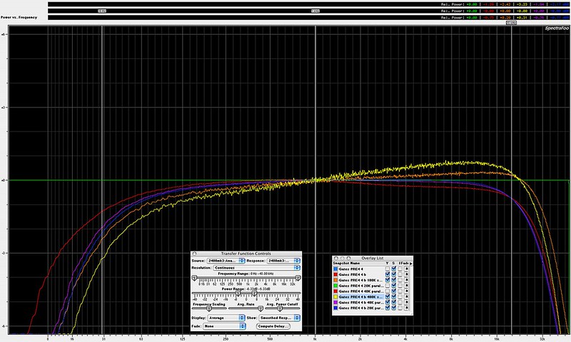
Response plots illustrating limits of feedback gain variance. This circuit has compensation caps everywhere which limit what you can change.
Click this link for larger pic
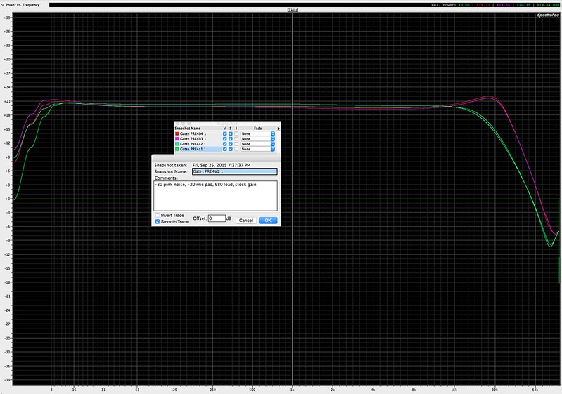
Response of the four units, you can see the input transformer difference clearly.
Click this link for larger pic
Click this link for larger pic
Click this link for larger pic
Click this link for larger pic
Click this link for larger pic
Click this link for larger pic
Click this link for larger pic
Click this link for larger pic
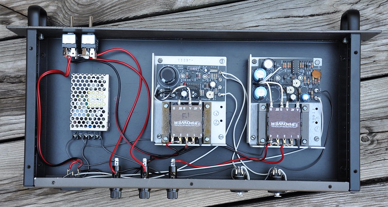
PSU. Required iso diodes to avoid latch-up through shared A-/B-. Added second DC output jack for use with theoretical additional preamp rack.
Click this link for larger pic
The can cap replacement/re-stuff was a serious pain due to use of point to point construction and Vector sockets, very little room to move in there. Fourth picture shows the deal. Here’s a separate thread on that.
How to: restuff an electrolytic can capacitor is where the above link is NOW - forum formatting changes have shit-canned old internal links like this! Have fun finding anything!
I took this pic before the clear coat was totally dry on the labels, so they look a bit milky.
Click this link for larger pic
Click this link for larger pic
Wiring has enough extra length to lay front and rear panels down flat for service.
Click this link for larger pic
Click this link for larger pic
Response plots illustrating limits of feedback gain variance. This circuit has compensation caps everywhere which limit what you can change.
Click this link for larger pic
Response of the four units, you can see the input transformer difference clearly.
Click this link for larger pic
Click this link for larger pic
Click this link for larger pic
Click this link for larger pic
Click this link for larger pic
Click this link for larger pic
Click this link for larger pic
Click this link for larger pic
PSU. Required iso diodes to avoid latch-up through shared A-/B-. Added second DC output jack for use with theoretical additional preamp rack.
Click this link for larger pic
Last edited:
")