Getting 1 megohm input impedance for a piezo pickup.

GroupDIY Audio Forum

Help Support GroupDIY Audio Forum:

This site may earn a commission from merchant affiliate links, including eBay, Amazon, and others.

VanGenz

Well-known member
Joined
Nov 20, 2008
Messages
80
Location
Norway
I have been looking at a rather cheap preamp from Thoman/Harley Benton called "Harley Benton Custom Line Bass DI-Expander" (Harley Benton Custom Line Bass DI-Expander)
to be used as a preamp for my friends double bass with a piezo pickup. The input impedance is only 680 kOhm but its a "well known fact" that the minimum input impedance for a piezo pickup should be 1 Mohm to avoid loss of bass response, which is even more important for a double bass than a guitar. I am aware that resistance and impedance are not the same. But if I put a 400kOhm resistor in series on the input of the preamp would the piezo pickup then "see" an imput impedance around 1 MOhm?
 
Well known?
===
adding 400k in series will form a resistive divider (pad) scrubbing off a few dB of level.

Better to replace the 680k resistor with 1M or more.

JR
 
I recall a similar issue a few years ago with a friend from another forum... we dug a little deeper and the input impedance of his preamp was fully constrained by the input resistive termination. In his case the simple resistor swap worked fine.

Perhaps dig a little deeper and determine what IC amplifier is involved. Don't make this harder than it needs to be.

JR
 
Well known?
===
adding 400k in series will form a resistive divider (pad) scrubbing off a few dB of level.

Better to replace the 680k resistor with 1M or more.

JR
i wrote "well known fact" beacuse a lot of info about piezo preamps claims minimum 1 Mohm input impedance.
 
I have been looking at a rather cheap preamp from Thoman/Harley Benton called "Harley Benton Custom Line Bass DI-Expander" (Harley Benton Custom Line Bass DI-Expander)
to be used as a preamp for my friends double bass with a piezo pickup. The input impedance is only 680 kOhm but its a "well known fact" that the minimum input impedance for a piezo pickup should be 1 Mohm to avoid loss of bass response, which is even more important for a double bass than a guitar. I am aware that resistance and impedance are not the same. But if I put a 400kOhm resistor in series on the input of the preamp would the piezo pickup then "see" an imput impedance around 1 MOhm?

Most likely, the input impedance of the DI expander is determined by a single resistor (680k) which, with a little knowledge, could probably be replaced by a larger one, as JR suggested. If this is not an option, I suggest making a cable that will have an additional resistor added to the series in its TS connector (on the DI extender side). You can even experiment with a few cables with different resistors and finally decide which variant is best for you.
 
Most likely, the input impedance of the DI expander is determined by a single resistor (680k) which, with a little knowledge, could probably be replaced by a larger one, as JR suggested. If this is not an option, I suggest making a cable that will have an additional resistor added to the series in its TS connector (on the DI extender side). You can even experiment with a few cables with different resistors and finally decide which variant is best for you.
Adding this resistor in series was my first idea. But I suspect we will go for the Fishman Platinum Pro EQ anyway which is a much better product and with 10 Mohm input impedance. Costs a lot more but he can afford it.
 
i wrote "well known fact" beacuse a lot of info about piezo preamps claims minimum 1 Mohm input impedance.
Somebody tell Harley Benton....

A piezo pickup is generally modeled as a voltage source in series with a capacitance. The important question is how much capacitance? From a quick search piezos can be as little as 200pF source impedance, but more typically 500-800pF (still worse than the 1,000pF plot). Caveat I still didn't find an actual bass guitar piezo spec sheet so still guessing.

Back last century when I designed my last active DI I used the highest available 1/4W carbon film resistor (single digit Meg Ohms) I don't recall the actual value I used.

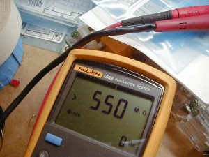
The last really high impedance input Z design I did was for my outlet tester. I used a 100M SMD resistor in series feeding a discrete MOSFET gate. It measured more than 500M ohm at 500V.
550-300x225.jpg


The simplest experiment for you to see if it makes a difference for your actual piezo pickup is to add a resistance in series and turn up the amp volume to make up for the signal loss. The cheapest good solution is to just replace the input termination resistor with a larger value. If you have too much money just buy a premium active DI while I expect even a cheap active DI will be > 1 M ohm input Z. The cheap one I designed years ago was.

JR
 
Adding this resistor in series was my first idea. But I suspect we will go for the Fishman Platinum Pro EQ anyway which is a much better product and with 10 Mohm input impedance. Costs a lot more but he can afford it.
You don't need all that gobbledygook. Eq is overrated. You just need an op amp in a die-cast box with a 3-pos toggle to adjust low-cut down to 40 Hz and very high input impedance. Of course there's no money in selling such a simple device so you probably won't find it for sale. It's a good DIY project though and this is a DIY website.
 
i wrote "well known fact" beacuse a lot of info about piezo preamps claims minimum 1 Mohm input impedance.
That is a very debatable subject. It's actually true that, in order to provide full LF response (-3dB@20Hz), the input resistance should be about 8 Megohm.
However, we're dealing with instruments that don't go down to 20Hz.
Standard tuning for a 6-string guitar has it's lowest note at 82 Hz. 4-string bass is 41Hz, 5-string is 31. So the latter could justify an inout impedance of 4+Meg.
But it's not the end of the story.
Instruments themselves don't have full LF response.
Typically, the double bass, which goes down to 35 (in drop-D tuning) has its acoustic response resonance located at about 70Hz. It means that the maximum efficiency is achieved about one octave above the lowest frequency. Numerous studies have shown that the sound of the double bass on the low strings has a small level of fundamental, the second harmonic being dominant.
The relatively low level of fundamental on bass instruments is not a complete absence ot it.
The same aplies to the guitar, where the resonance happens between 110 and 200 Hz, so significantly above the lowest string.
That shows that for a faithful reproduction of sound when using a pick-up, full LF response is not a requisite. The pick-up system is typically capable of picking very low frequencies, with the only restriction of the high-pass effect of the load it is presented with.
The same consideration is what allows bass amps equipped with 10 inch speakers to produce a credible sound even on the low-B string.
Now I know some (Whoops) advocate 10+Megohm, but I don't. IMO it makes the mechanical noise (pick attack) too prominent.
I've never felt frustrated with a piezo guitar into 1 Meg. Anyway, each one their own. :)
Just the same, attenuation of high frequencies in some cases does not mean that they are perceived as missing.
The tone of an electric guitar can be clearly identified with the frequencies above 4kHz being severly attenuated by the inherent roll-off of a typical guitar loudspeaker.
 
the minimum input impedance for a piezo pickup should be 1 Mohm to avoid loss of bass response, which is even more important for a double bass than a guitar. I am aware that resistance and impedance are not the same.

1 mega is the standard input impedance in most Active DI boxes but you will see that DI boxes specifically made for Piezo pickups have an input impedance of 5 to 10 Mega.

I like to use 10Mega for all piezo pickups, I find 1 Mega to be too low
 
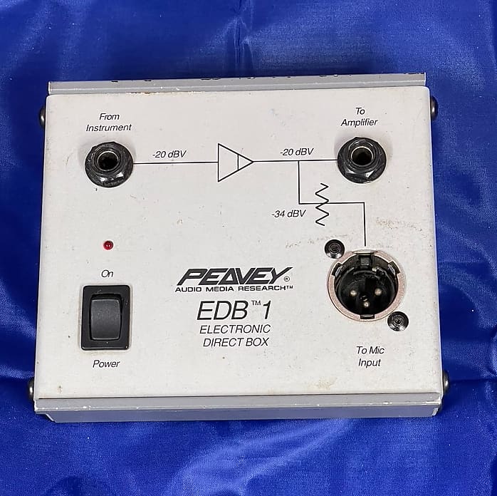
Many customers believe 1M is too low, and the customer is always right, even when wrong. I used more than 1M in the cheap Peavey/AMR active direct box because I could with no cost penalty up to the single digit M ohm range.

obkclkg4r6mgbp0cgoyo.jpg


powered from internal 9V battery, 16vac wall wart, or phantom power...

JR
 
Radial offers some good DI boxes specifically designed for Piezo pickups like the StageBug SB-4 which has 5 Mohm input impedance:

https://www.radialeng.com/product/stagebug-sb4
There's also PZ-DI model which offers a 10 Mega setting for Piezo pickups:

https://www.radialeng.com/product/pz-di
These are Radial statements on both of them:

"The PZ-DI has a variable load selector switch that allows you to set the input impedance of the direct box (...) The third setting is an ultra-high 10 meg ohm impedance that is specifically designed for piezo transducers, helping compensate for the harsh or squawky tone that can occur when a piezo is connected to a lower impedance input."

"Unlike typical direct boxes, the SB-4 features a very high 5 meg ohm impedance that smooths out troublesome peaks that give piezo transducers a bad name. This higher impedance also broadens the frequency response for a more natural and pleasing sound."


With my vast experience being a sound engineer for many years, I used most DI boxes available in the market both in the studio and in Live Sound and I have to say that as far as Piezo pickups is concerned I've found that Radial statements are correct and represent my experience when using a Piezo with a 1 Mega input DI box when compared to 5 Mega or 10 Mega, and specially with instruments like Double Bass the difference/improvement is quite dramatic.
Like Abbey said we had this conversation in the past and we disagree, but as far as my opinion goes I can only say that it's quite noticeable and if someone is in doubt you should do the test for yourselves, record the same line with both DI's and compare for yourselves.
As far as I'm concerned I have standard 1Mega input DIs in all the Venues I go, if that worked for Piezo pickups that would be preferable to me as I didn't need to carry my own (higher impedance) DI boxes, but that doesn't work well for Piezos and the sound suffers, so have to go through the extra trouble of bringing my own Di boxes.

This is also pretty clear if someone checks the input impedance of Piezo preamps, the ones that come installed in the guitars, if you check the schematics you will notice that Piezo preamps are normally designed with 5M, 6M or 10M input impedance, so it makes sense when a piezo preamp is not used to use a DI box with the same load.

Just one last point to say that the well known Countryman Type 85 Di box has an input impedance of 10 Meg also and it's recommend by some high quality piezo pickups manufacturers like Carlos Juan and Yamahiko:

https://carlosjuan.eu/#&panel1-1
https://www.yamahiko.info/en/
 
Somebody tell Harley Benton....

A piezo pickup is generally modeled as a voltage source in series with a capacitance. The important question is how much capacitance? From a quick search piezos can be as little as 200pF source impedance, but more typically 500-800pF (still worse than the 1,000pF plot). Caveat I still didn't find an actual bass guitar piezo spec sheet so still guessing.

Back last century when I designed my last active DI I used the highest available 1/4W carbon film resistor (single digit Meg Ohms) I don't recall the actual value I used.

The last really high impedance input Z design I did was for my outlet tester. I used a 100M SMD resistor in series feeding a discrete MOSFET gate. It measured more than 500M ohm at 500V.
550-300x225.jpg


The simplest experiment for you to see if it makes a difference for your actual piezo pickup is to add a resistance in series and turn up the amp volume to make up for the signal loss. The cheapest good solution is to just replace the input termination resistor with a larger value. If you have too much money just buy a premium active DI while I expect even a cheap active DI will be > 1 M ohm input Z. The cheap one I designed years ago was.

JR
Wow, an insulation tester to measure a MOSFET's input resistance, good idea but I can't help feeling like you were using a 1/4 " drill bid to pierce someone's earlobe to use an earing. How did you connect it to the MOSFET? with a 100 M resistor plus the gate input current will be very low, but how was the MOSFET able to withstand a 500V VGS? I am intrigued....
 
Wow, an insulation tester to measure a MOSFET's input resistance, good idea but I can't help feeling like you were using a 1/4 " drill bid to pierce someone's earlobe to use an earing. How did you connect it to the MOSFET? with a 100 M resistor plus the gate input current will be very low, but how was the MOSFET able to withstand a 500V VGS? I am intrigued....
This was a project I abandoned several years ago. For TMI click this link OD-1 this website explains it all including a schematic.

I wanted to design an outlet tester that actually works to detect the dangerous condition of "reverse polarity bootleg ground" (RPBG). The ubiquitous 3 lamp outlet tester does not detect that fault.

I needed the extremely high impedance to pass UL insulation tests. So as far as they are concerned it is an open circuit (>500M @ 500V). That is difficult enough that it required a specialized tester to confirm. I abandoned the project because it was looking like it would cost me several tens of $k more to persuade UL to approve it. I wouldn't sell an outlet tester without UL approval. UL approved the cheap 3 lamp tester (that doesn't actually work) by making them add a caveat in the instructions that it can't detect multiple simultaneous fault (like RPBG).

This extremely high impedance input accepts a finger contact that serves as a relative environmental reference. The tester compares the reference voltage of the body (roughly 0V) to the outlet leads to detect for energized leads.

Since this would, need to sell for <$20 retail the odds of me ever making my investment back were remote. So I shared it with the world.

JR
 
I'd given up on piezo style elements because of inherent problems associated with matching, what brought me back to looking at them again was coming across K&K pickups, they take a simple approach - fit three piezo elements together in parallel - firstly it gives you a richer spread of source from across the soundboard and secondly the input stage sees a better signal because all three are in parallel.

I would try two on a double bass, under the bridge feet, sandwiched between the instrument top and the foot of the bridge - the extra pressure on the element helps with output and helps with the overall tone of the signal, also helps to keep feedback down. Try two elements it might just be enough !

Another aside - just sticking a piezo element onto the soundboard will sound awful, they need to be superglued inside, double sided tape doesn't work as it damps down energy transfer - another reason for banging them under the foot of the bridge is that's where it's all happening and where the energy transfer takes place.

I'm sure there are many technical reasons for not putting multiple piezo's in parallel but it works in the real world and the amp or Di box seems to prefer it.
 
Last edited:
I'd given up on piezo style elements because of inherent problems associated with matching, what brought me back to looking at them again was coming across K&K pickups, they take a simple approach - fit three piezo elements together in parallel - firstly it gives you a richer spread of source from across the soundboard and secondly the input stage sees a better signal because all three are in parallel.

I would try two on a double bass, under the bridge feet, sandwiched between the instrument top and the foot of the bridge - the extra pressure on the element helps with output and helps with the overall tone of the signal, also helps to keep feedback down. Try two elements it might just be enough !

Another aside - just sticking a piezo element onto the soundboard will sound awful, they need to be superglued inside, double sided tape doesn't work as it damps down energy transfer - another reason for banging them under the foot of the bridge is that's where it's all happening and where the energy transfer takes place.

I'm sure there are many technical reasons for not putting multiple piezo's in parallel but it works in the real world and the amp or Di box seems to prefer it.
Putting three in parallel will make the source impedance lower (3x the C, moving in the right direction) while the output from the individual pickups will be passively summed with 1/3 weighting each.

JR
 
just sticking a piezo element onto the soundboard will sound awful, they need to be superglued inside,

I thought most (at least for acoustic guitar) were stuck under the bridge, and the string tension kept the pickup clamped between the soundboard and bridge.
At least that is how some of the Fishman pickups are installed:
Fishman undersaddle pickups

A friend of mine got one of those in his Martin with a preamp installed inside as well. Sounds great through a DI box.
 
I'd given up on piezo style elements because of inherent problems associated with matching, what brought me back to looking at them again was coming across K&K pickups, they take a simple approach - fit three piezo elements together in series - firstly it gives you a richer spread of source from the soundboard and secondly the input stage sees a better signal because all three are in series.
Are you 100% positive they are in series? i really think they are in parallels. Connecting them in series make them quite prone to picking interference.
I would try two of them on a double bass, under the bridge feet, sandwiched between the instrument top and the foot of the bridge
The recommanded placement is in insertion in the bridge between the hip and the knee (the parts that surround the kidney).
It is certainly not the best place in terms of level, though. Placing the pickups under the feet probablky results in increased level, but the stability of the bridge seems compromised.
- the extra pressure on the element helps with output and helps with the overall tone of the signal, also helps keep feedback down. Try two elements it might just be enough
Looking for the results of your experiment.
Another aside - just sticking a piezo element onto the soundboard will sound awful, they need to be superglued inside, double sided tape doesn't work as it damps down energy transfer
Not only that. Piezo pickups sense the difference of acceleration between both sides of the pickup. Because they are very light, there is not much difference, hence not much level, unless you load them with a weight.
I've done that on my piano; adding the weights increase the level by about 20 dB.
So the proper way would be supergluing a weight on the pickup and supergluing the whole to the soundboard.
 
Last edited:
I thought most (at least for acoustic guitar) were stuck under the bridge, and the string tension kept the pickup clamped between the soundboard and bridge.
At least that is how some of the Fishman pickups are installed:
And many electroacoustic guitars come equipped that way. mainly because they have good level and low feedback.
However, a number of musicians don't like the "quack" of undersaddle p/u's, and prefer a soundboard transducer. Unsersaddle p/u's typically pick-up the string vibration and ignore the wave propagation in the soundboard that is a large part of the timbre.
The sound that's picked up by a soundboard transducer retains some of the acoustic effects of propagation in the soundboard. What's more multiple pickups sense a larger "picture" of the instrument.
Since they pick up the soundboard vibrations, they are more prone to feedback.
 
Back
Top