Guess the transformer?

GroupDIY Audio Forum

Help Support GroupDIY Audio Forum:

This site may earn a commission from merchant affiliate links, including eBay, Amazon, and others.

bruce0

Well-known member
Joined
Jan 24, 2010
Messages
1,065
Location
Boston
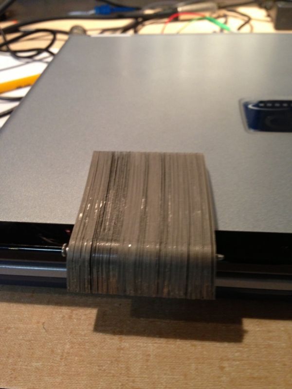
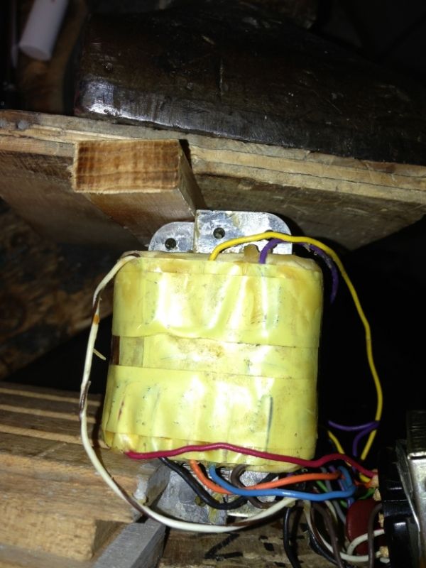
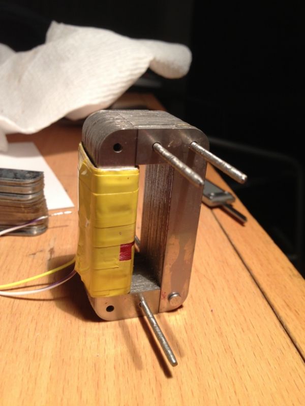
I know what this is, but thought it was interesting, and beautifully made... Anyone want to take a guess at what it is before I reveal it?

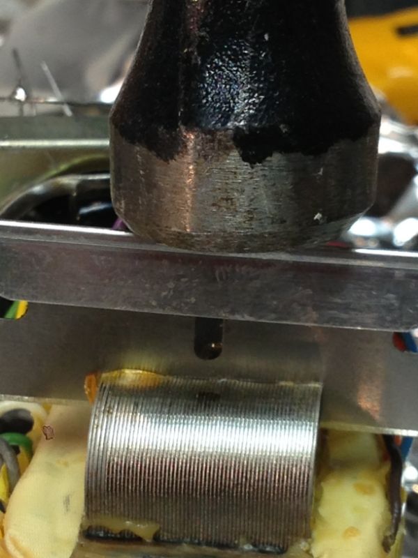
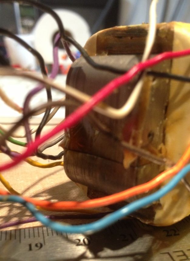
It has lots of taps. In a 3.5:1 stepdown configuration it is 2.6 H on the primary (21 ohms) and 190mH 5 ohms on the secondary.  If it is nickel the inductance is pretty low, the wire seems to be sort of #34 or #32 (some of the coil is exposed) but I don't know.

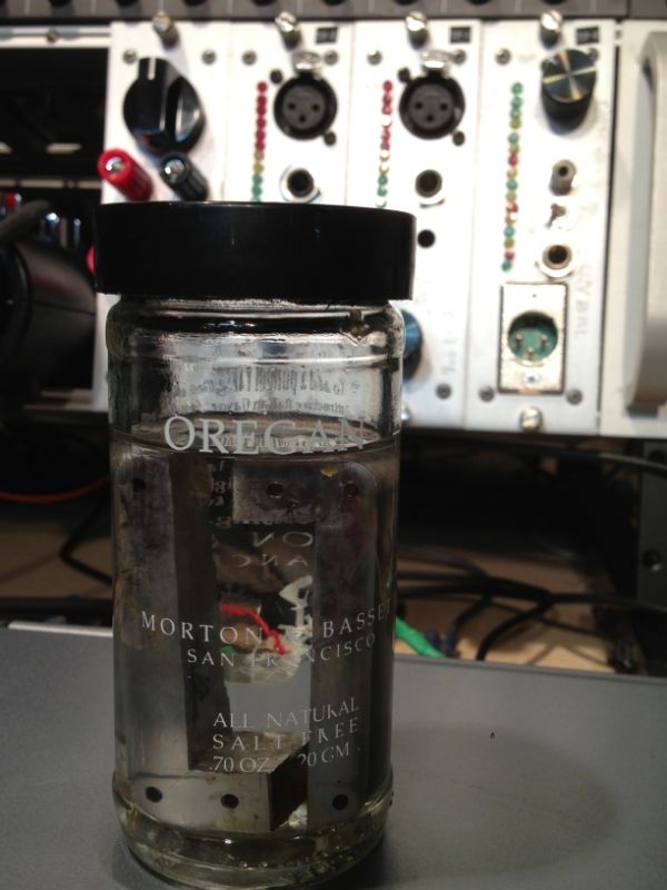
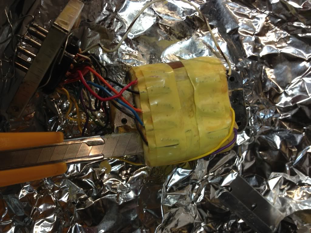
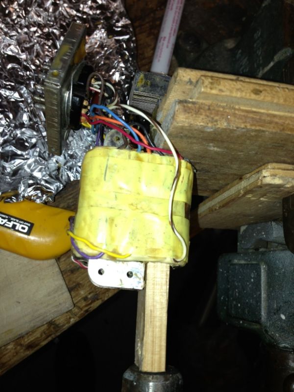
I de-potted it from wax, but it works, so I thought I would stop here.

More things I don't know, that maybe someone else does:
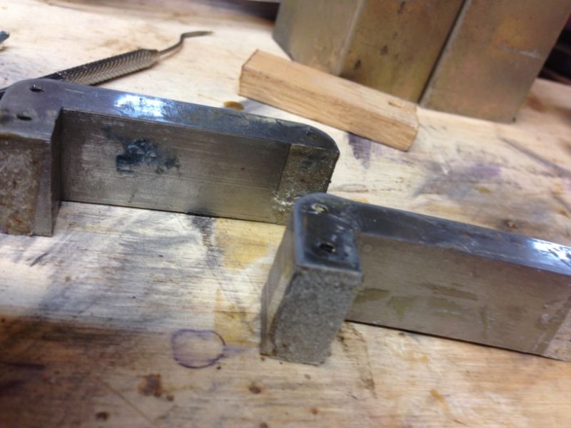
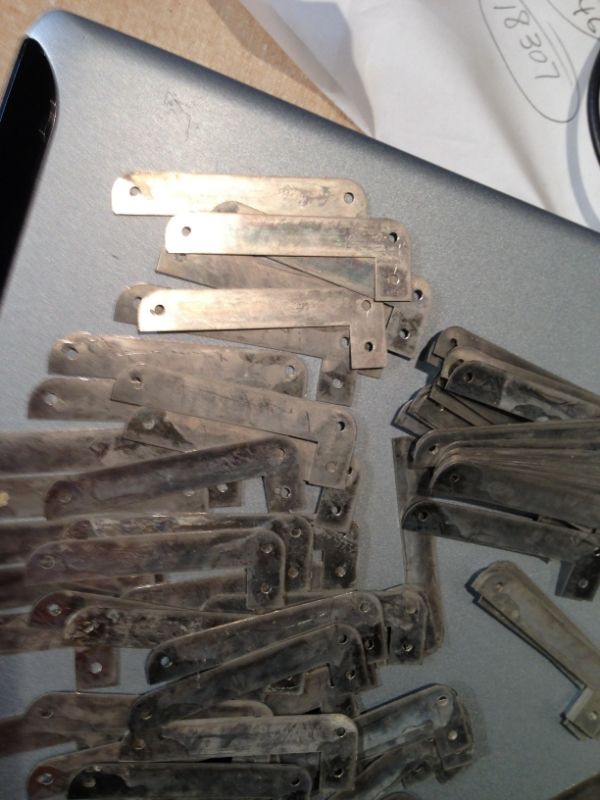
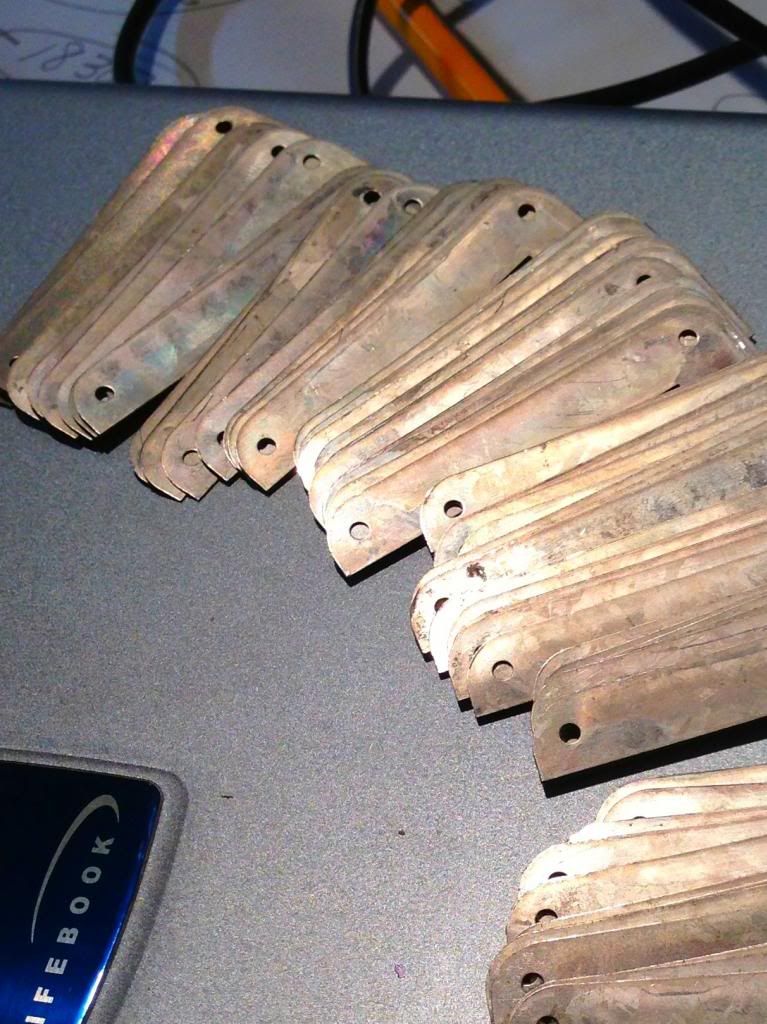
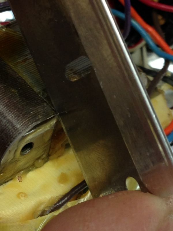
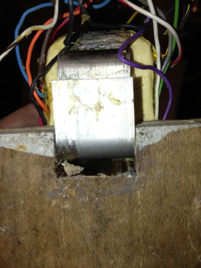
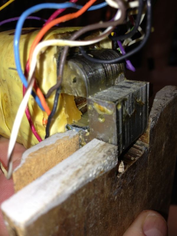
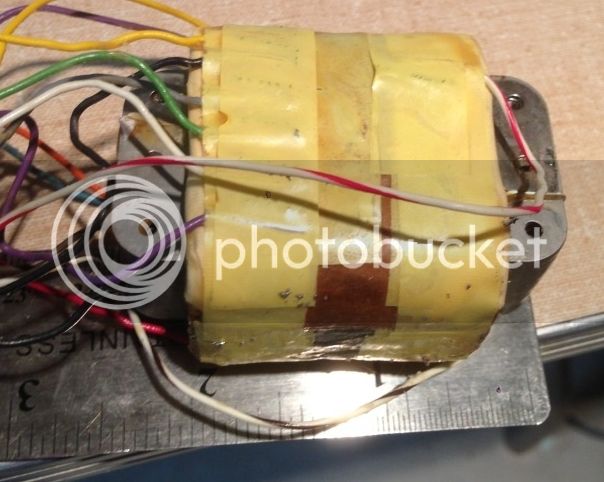
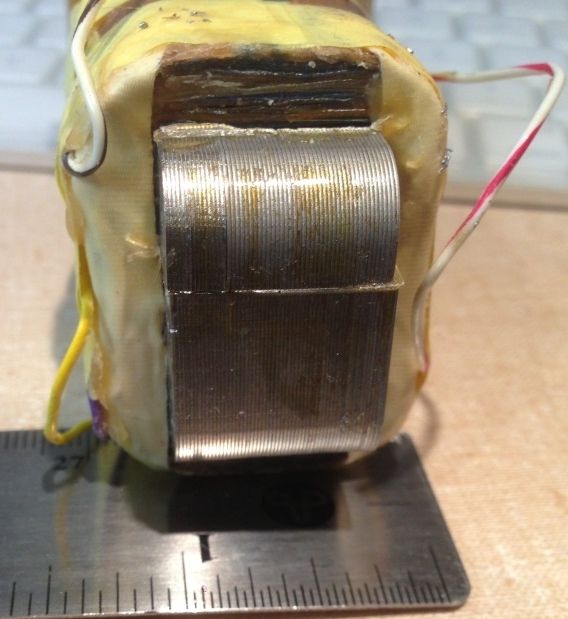
  • Does the shiny surface imply that it is nickel? (it is many years old, but no rust). Maybe the low inductance is because it is gapped?
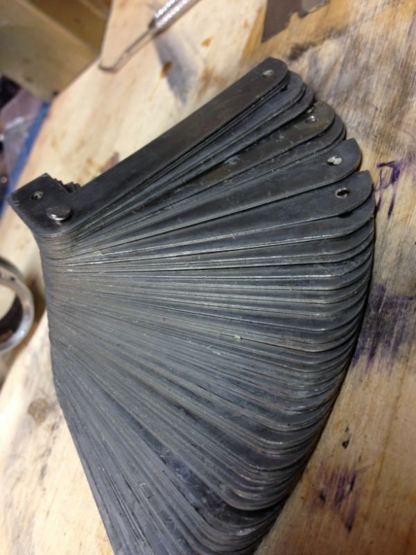
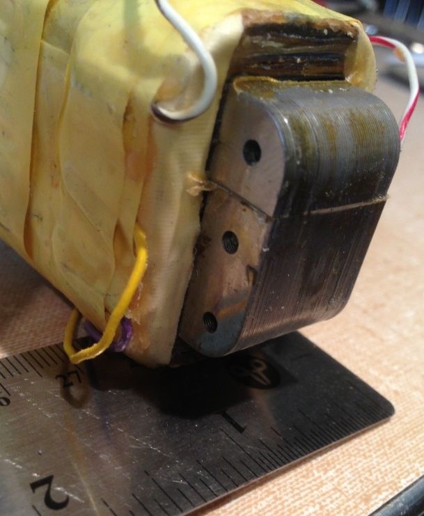
  • Do the cracks at the end (which seem to have paper spacers, and seem to be glued) mean that it is gapped?
  • It has lots of taps, but in a 3.5:1 stepdown configuration it is 2.6 H on the primary (21 ohms) and 190mH 5 ohms on the secondary.  I assume the low inductance would indicate it was gapped too.
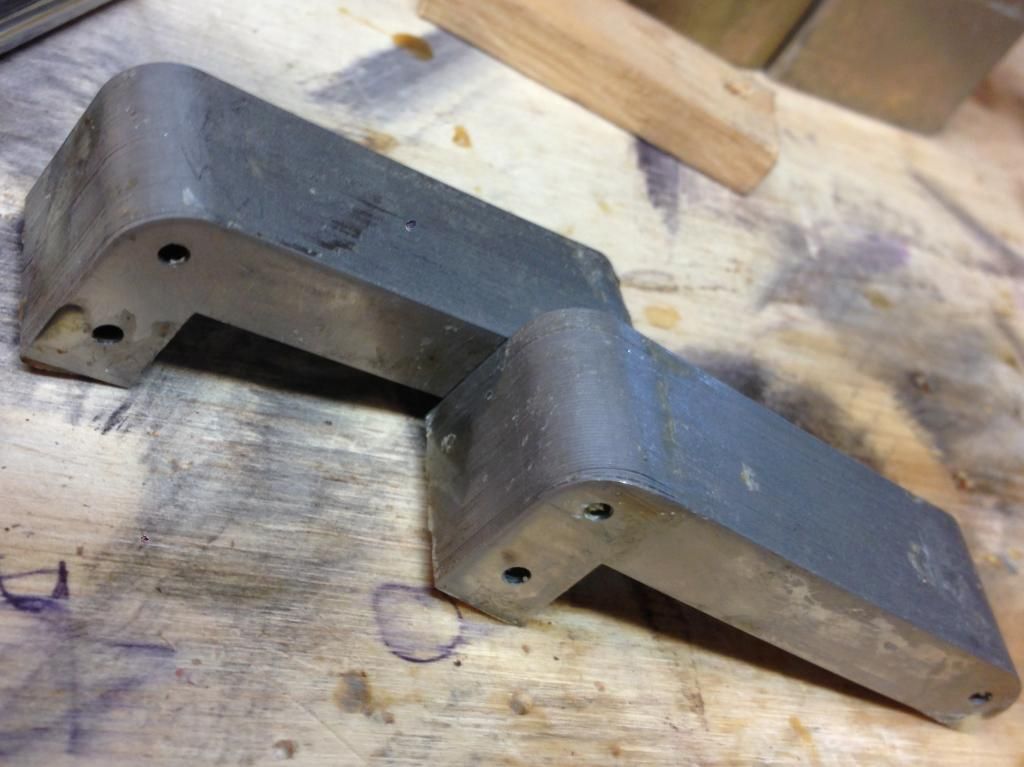
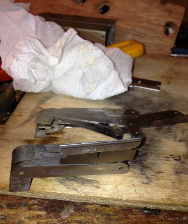
  • Is it wound like a C core? (the laminations seem to be L's not overlapped and gapped with paper at both ends by and glued).
  • Suggested uses?


Even at 20hZ it takes a lot to saturate it.
Frequency response driven by low impedance is within 0.35dB of my test gear's response curve.  Driven by higher impedance (3K) it gets a a little ugly at 20Hz with higher levels.


d2f01e3b-9e68-4ac2-9b1c-9f850d1c6692_zps5fb58bfb.jpg


null_zps796fed37.jpg


null_zps4b75fa43.jpg


null_zps51fd73b9.jpg
 
Could it be anything other than Peerless?
All your points are correct. Is it intended for a single ended power amp?
 
those are 12 L lams,

you can use them to build a s 217 D for Pultec,

or use it the way it is without a feedback line amp,


looks like a 16402

did you break into my teepee last night?

gotta quit smokin the peace  pipe, switch to something that won't make me nod out, anybody have any heroin for sale? something pure that won't get me hooked?


CJ said:
those are 12 L lams,

you can use them to build a s 217 D for Pultec,

or use it the way it is without a feedback line amp,


looks like a 16402

did you break into my teepee last night?

gotta quit smokin the peace  pipe, switch to something that won't make me nod out, anybody have any heroin for sale? something pure that won't get me hooked?


It is interesting that these are "12 L" lams, I wonder if it is the same alloy as you found in the 16402 (which from reading your thread, you decided was GOSS (grain oriented silicon steel)). 

I wonder how I can check the permeability of this material without pulling it apart.  As a gapped core, I think I may be S.O.L., because even if I figure out the turns from wire size and DCR, I will never figure out the gap size right?  Or is there a trick.

So (game over) it is an Altec Peerless 15189 Hybrid telephone signaling transformer (you can get these pretty cheap on Ebay), and if it does have lams to make an S-217-D, that is kind of cool.

How can I check if they are the right lams?
Did your S-217-D build that you beautifully documented in another thread produce specs that were in line with the original?

FYI:
I did measure the lams, which measure out to your specs in the other thread, as close as I can tell before pulling it apart (gap is not known).  You say the "S 217 D" had a 7/8" stack, this stack is  .770" (a little over 3/4) and 56 lams (actually one side is 56 the other 54... construction error). So .770/56=0.01375" thick lams.  Does that sound correct?

I guess it will take more than one of these to make a S217D stack, and unfortunately I will need to make new bobbins because those will be too narrow for the stack I guess.

Hints on dissolving/removing gap glue (hard amber) without damaging the lams.  Wax just melted to a gel which I could brush away, but the glue is like amber.


Not sure I understand teepee... but I think your teepee is safe... (if that is the place with the pliers, hacksaw and heat gun...), I just had a bunch of these 15189's and wanted to see what made them tick, and figure a way to use them.

Driven with a low impedance op-amp, it has really flat performance (-0.25 ish dB for full bandwidth I can test), but at higher impedance not so good, I guess it would need to be converted to ungapped  to get high enough inductance to use in a tube output stage.
 
wow, thanks for the new part number, i knew that there  must be other Peerless iron with 12 L lams but i did not want to start buying random transformers to find out,

gaps are easy, they only use a few sizes for audio, usually 1 mil, 3 mil or 5 mil,

rare to see anything over 5 mil unless you are talking about chokes for power supplies,

the math for computing gaps is horrific and inaccurate, so engineers just try different paper til they get what they want, it is 10 times faster and very accurate, they just measure the magnetizing current til they get what they want,

there is also a graphical method if the transformer is too big to keep trying gaps, it involves plotting DC amp turns divided by magnetic path length for the Y axis and DC amp turns divided by the gap length for the X axis, then you draw a line to the knee of a typical BH curve, this divides the bias between the core and gap evenly as to optomize the gap and therefore Q, but you do not always want max Q, you may want to tune an inductor for a specific roll off, so this method is usually reserved for radio and audio inductors, now audio inductors usually are wound on toroids so no gap changes are possible other than changing materials, so the graphical method is seldom used in audio i would think,

small cores have a natural airgap of about 0.5 mil to 1 mil so you don't really need any gap at all if you use a butt stack for EI lams, the 12 L lams are probably steel and that is a pretty hefty stack, Peerless was the Cadillac of the transformer makers back then, better than Triad and UTC, so they did not skimp on steel,

if you want to check perm, use the PRR method for checking turns, you squeeze in about 10 turns of small wire in between one leg of the core, inject a say, 10 volt signal at 1 k hz, measure the highest voltage you get off the leads, compute the turns of the the winding on the transformer, measure inductance, and use the formula for perm to get a rough estimate, there is a huge difference between steel and Ni so it is easy to figure out,

Adrian had a chemical method where he used copper sulfate and then looked at the reaction on the steel, but who has copper sulfate laying around? i used to have some crystals in my Gilbert chemistry set, but we do not school our kids as good now days so the chemistry sets and heath kits are a thing of the past, guess they are afraid of the kids making roadside bombs or something,

 
Well the phone company had on the order of one transformer for every 3-5 phones installed didn't they, so there should be some out there...

So the PRR method ( I searched but didn't find it)... is it that I inject the signal on the existing windings (Measuring 10V rms at the primary terminals), and measure the signal off the 10 turn "squeezed in" winding used as the secondary? or the other way around? 

The gap has paper in it, and hard brown glue... Acetone?
bb
 
CJ said:
wow, thanks for the new part number

I come bearing gifts... call it a little donation to the cause...  You seemed so pleased with the part number that I cracked a 15192 just now.

null_zps404ec6de.jpg


(Slightly distorted image photobucket 800x600 conversion not very good)
null_zps34e19292.jpg


So now there are 2 part numbers.

Maybe you could tell me how to get them UNGLUED ?

null_zps5ecebded.jpg


I cracked a piece of this off and it has been sitting in acetone for an hour... no effect. An 850 deg. F iron burns/crumbles/melts it a bit, but those temps would risk the lams.

How do you deal with the glue?
 
wow, that is some type of weird glue,

if the heat does not do it the only other thing i can think of is to soak it in paint remover for a few days,

you will lose the coils but if you want the lams that might be the price to pay,

or you could grind off the coils and try to pry apart the core from the inside,

 
Am I seeing things or were this pair sold today:
http://www.ebay.com/itm/ws/eBayISAPI.dll?ViewItem&item=140969614958&catId=293&item=140969614958

Here is the spec sheet for both;

http://www.telephonecollectors.info/index.php/browse/document-repository/catalogs-manuals/doc_download/427-altec-xformers
 
MatthisD said:
Here is the spec sheet for both;

http://www.telephonecollectors.info/index.php/browse/document-repository/catalogs-manuals/doc_download/427-altec-xformers

If you strap two 15189's together they are supposed to be 100hz to 6K hz (as a pair), on their own 100-10K hz, but my tests with transistor output stage are basically flat 20-20K (-0.25db), I think they are over engineered, or spec'd for 600Hz sources or something.
CJ said:
wow, that is some type of weird glue,

if the heat does not do it the only other thing i can think of is to soak it in paint remover for a few days,

you will lose the coils but if you want the lams that might be the price to pay,

or you could grind off the coils and try to pry apart the core from the inside,

I think since the lams are butted, I might be able to use rods through the holes to put them under tension, and then maybe get them to crack open.  It is well bonded.

I think it is epoxy, I will do some online research and report back.  I don't want to nick them all up (I am assuming they have some sort of insulating finish? but it doesn't look like it, I thought lams were supposed to be insulated).
 
That is probably frequency response at the maximum operating conditions as listed.

Like you say, you could try to pull or push the two halves in opposite directions.  Maybe in a vice with a makeshift jig made of planed timber to get the pressure on opposing halves.
 
I have been looking at things for dissolving epoxy... and I find it is pretty nasty stuff, and not very effective.  Freezing and cracking with sharp impact seems popular, but of course I am concerned about deforming the lams.

Update: Turns out that the glue is probably epoxy, which is bad, but it seems that Peerless epoxied wax paper into the gap, which is good.  So I clipped off the glue with flush clippers, and it just popped off pretty clean, and an Xacto blade tapped into the gap split both ends pretty well.  Then pressed them out with a vise (one stuck... some epoxy between the coil and lams) but a little worrying... and it came free.  Tapped it out with a block of wood.

CJ:  you can see a few lams got nicked when I cut the gap on one end, are these lams now unusable, or should I work on them in some way to fix the damage?  Or is the damage not too bad?  How sensitive is the lam face when they are staggered.

Some damage (is this ok, do I need to file the faces to be perfectly flat, or just leave them?)
null_zpsd6080bae.jpg


Since the lams are butted, they come out in nice easy pieces (much easier than interleaved lams)
null_zps0f03a9a5.jpg

null_zps39084180.jpg


Spicy Lams with Oregano... (soaking them in Acetone and Alcohol, hoping to loosen overnight).  Any guidance on loosening lams.
null_zps2fb082d3.jpg

 
those nicked alms will be fine,

that is not supermally so they take more abuse without a perm loss,

steel lams are coated with a thin insulation layer, so if you nick one end, the flux has to travel all the way around, back and forth, to cancel out, the higher the freq, the less loss at the damage point,

we used to install drive pins at the transformer place where i worked,

you assemble the transformer with Al tie plates going from top bracket to bottom bracket and tighten the core bolts real good, then you drill about a 1/2 inch hole into the lams at the corners of the transformer, or in 3 places top and bottom, both sides, for a 3 phase unit,
so you might have 12 drive pins which means 12 holes 1/2 inch deep in the core, the engineers say you lose very little by doing this, so your nicked lams will be alright,

drive pins are 3/8 inch long rivet like pins that have a raised swirling pattern which secures the outer lams to the tie plates so the brackets and lams stay together,


Turns out soaking in isopropyl alcohol and acetone softens the glue some, and it peels off.  A sharp razor blade (Xacto is too thick) sliced down the joint begins to separate the Lams about 1 out of 5 times (so it takes about 5 strokes a lam).  Once they begin to separate, you can run just the beveled part of the blade all the way around till it pops free, with no permanent bend to it.  About 10% of them were really tough to get started, but the rest really just popped apart.
null_zps56a22147.jpg


It does seem like there is a bend to all of the lams, I think they may have been punched near the end of the roll of sheet metal or something.  This bend was visible in the core before it was separated too.
null_zps1441755d.jpg


There is some rainbow coloration due to heat treating perhaps?  Hard to photograph.
null_zps4f448372.jpg


Image saturation enhanced:
null_zpsa41d283c.jpg


One of the coils was epoxy'd partially to the lams and so the coils got a bit damaged when removing them.  But when I do the other transformer (the 15189) I am going to try to save the coils.  I am wondering if I just remove the lams, and re-insert them in the same coils with "alternating" rather than "gapped butt" joint, will I get a transformer that has high enough inductance to be used on one of gyraf's SRPP output stages.

Final pic, "Sliced lams with Oregano"

null_zpsd26311fc.jpg
 
So CJ, if I want to make a S-217-D...

I need to make the bobbin formers, and the paper bobbin... What do I make that out of? Glue and paper? Wax and paper?

Where do I get .005 nomex, I searched and I think I must be calling it the wrong thing...

Is there a particular tape you recommend?  Will Kapton tape work?

I have to get some more lams from the other transformer, and then I can put together a 7/8 inch stack and measure permeability... you said yours was about AL 20,000?
 
Here are directions for pulling apart one of these  Peerless telco transformers in detail.

After popping open the case with a thin screwdriver (the bottom comes off) heat the whole case (I use a heat gun) and gently tug the transformer out of the case.

Warm up the transformer, and use an old toothbrush to brush the wax off, then use heat gun and paper towels to clean it off.

Then use a razor blade (not xacto, too thick, bends lams) to separate the but joint, as pictured below (start at the corner, and then go across the whole joint).  The second joint is easy because it cracks a bit when you move the first.

null_zps46b5c620.jpg

null_zpsfa6b83f0.jpg


Sometimes there is glue between the core and the coils, I used a long box cutter to separate them.  You can only do 3 sides, which can be enough (once there was glue on the inside of the L and it munged up the coil during disassembly (munged is a technical term))

null_zps622545b6.jpg


Make a hardwood plank with a slot exactly the width of the core (tight fit)
null_zpsbfa75a4e.jpg


Use a vise, and a small block to press half the core through (this only works with gapped but joint laminations).
521b9887-f7ad-4717-93cc-f7656ce85c7e_zps622a836e.jpg


After pressing, from here you can tap the lams out with a small wooden block and mallet.
null_zpsc27be693.jpg

null_zpsb2851584.jpg


When splitting them apart, don't press the razor through, just put the edge in and slide it around the outside.  See video below if that is not clear.

f221e203-6bf0-451b-a06c-fea0f0a2b555_zps280cc868.jpg


Video...
http://s1221.photobucket.com/user/Bruce0/media/Trafo/BE390DF1-8074-4205-A300-A3E3B3B13827-120-0000012C7125C107_zps054940a3.mp4.html
 
CJ measured primary inductance of 220H based on 3150 Turns (2 coils, 1575 turns each).

That implies that the AL value for the core was 22000.  His core was 0.875" which I think would measure higher due to greater cross section?  But still that seems pretty high.

I put 100 turns on a cardboard coil former, and measured the inductance at 56.2mH, giving an AL value of 5620 for the core.  The core stack is 0.834" on one side, and slightly more on the other side.  I don't know how much it would be increased by a tighter pack or a thicker stack of lams.

CJ?  Am I reading your core data correctly?  Do I have lams of the wrong material?


null_zps264d4fe5.jpg
 
EDIT:  I have been playing with this some more today, and I just can't make heads or tails of it.

I can understand that I get different inductances relative to frequency, but I can't figure out why the inductances look so high and weird.  Why the inductance is EXACTLY the same even when the number of turns is doubled.

The forumula I am using is =(V/I)/(2*pi()*frequency) in Excel, to get L  but it is producing results I can't figure out.

bb

CJ said:
just run it through the coil and measure the current and voltage across the coil at 100 hz,

L=(V/I)/2pif, so for 100 hz you would have L=(V/I)/628

Ok I did this.  I made a circuit (sig generator) - redprobe - resistor - yellowprobe - inductor -ground/common

And I measured voltages peak to peak and rms at both redprobe and yellow probe, and subtracted them and used the Voltage across the resistor to get current (I).  Then used your formula, compiling the following table.

RMS and Peak to Peak results are the same (thank goodness)
And I can calculate an L (which seems too high for 200 turns)
But when I try to get AL (by dividing by turns squared) the number I get is confusing.

Two things confuse me. 
1) The L (inductance) seems to be the same regardless of whether I have 100 turns or 200 turns.  I thought more turns more inductance.
2) I tried to solve for AL and had some trouble.  Do I multiply by 1,000,000 or 1,000,000,000 because both provide an answer that makes no sense.

Do these numbers make sense, or ... did I wire something wrong?
 

Latest posts

Back
Top