Guitar Amplifier Project - HT Voltage Question

GroupDIY Audio Forum

Help Support GroupDIY Audio Forum:

This site may earn a commission from merchant affiliate links, including eBay, Amazon, and others.

brendandwyer

Active member
Joined
Jan 26, 2007
Messages
40
Location
CT, USA
I'm working a modded version of Marshall's 2204 circuit.

My voltage into the first filter capacitors is 444, which is much higher than i would have expected, and higher still than i would have expected considering my wall voltage is 120.2 VAC.

Can anyone help me try to troubleshoot this?

Thanks a bunch
 
I'm not familiar with the specifics of that particular amp but 444VDC could easily be correct. Transforms can step up / down AC to just about any voltage.

Be careful though. That's high enough that under the wrong circumstances you could permanently hurt yourself. Make sure the chassis is earthed and work somewhere where your body does not have a really good path to ground (for example don't have one hand on a faucet while using the other to poke around inside with a metal probe).
 
Thanks for the tip but the transformer has been faithfully spec'd to the original and the voltage from the secondaries seems consistent with that spec.

I'm actually wondering if my choice of rectifiers could be part of the problem...1N4007...in all my projects I've never had the post rectifier voltages differ this much from expectation.
 
What is the voltage on the secondary, and what are you expecting?

A 50W JCM800 often uses 690V CT with half wave diodes. 444V DC would be pretty reasonable out of this.
 
> voltage into the first filter capacitors is 444, which is much higher than i would have expected,

I don't know what to expect. I don't have every Marshall memorized. You don't say the VAC of your faithful PT.

Mark Huss' "dead stock" 2204 shows 468V DC for "exactly" 120V AC. 
https://mhuss.com/MyJCM/
https://mhuss.com/MyJCM/JCM800_2204.pdf
 
more important is bias voltage,

what kind of tubes? JJ  6550?
Mullard EL 34?
GEC KT66? 

lets say el 34 at 25 watts max p1 disp

.7 x 25 = 17.7 watts idle,

17.5/444 = 39 ma per tube,  measure OPT  DCR  unplugged and caps drained,

CT to each plate, plug in, warm up 20 minutes, measure V drop across OPT CT to plates and adjust bias control


ok.  I'll try to answer all the questions

The PT is 120v AC and is spec'd to deliver 350vac on the secondaries.  I'm reading 354vac

This has a solid state recitifer using 1N4007

It currently has JJ EL34L's.

I have it biased to right around 37ma.

If my plate voltage is reasonable, i'll cross it off the list of things to worry about.

Thanks!

 
Seems reasonably to me.  I have a model 1987 which is lower voltage of 390 but usual for that year of 1970.  450 to 460 was more common in the later era of 2403  2404 and later JCM 800
 
brendandwyer said:
ok.  I'll try to answer all the questions

The PT is 120v AC and is spec'd to deliver 350vac on the secondaries.  I'm reading 354vac

This has a solid state recitifer using 1N4007

It currently has JJ EL34L's.

I have it biased to right around 37ma.
So you have 444V B+ with EL34's biased. That's good. EL34's are commonly used with 470-480V B+.
 
Awesome thanks for everyone's help.

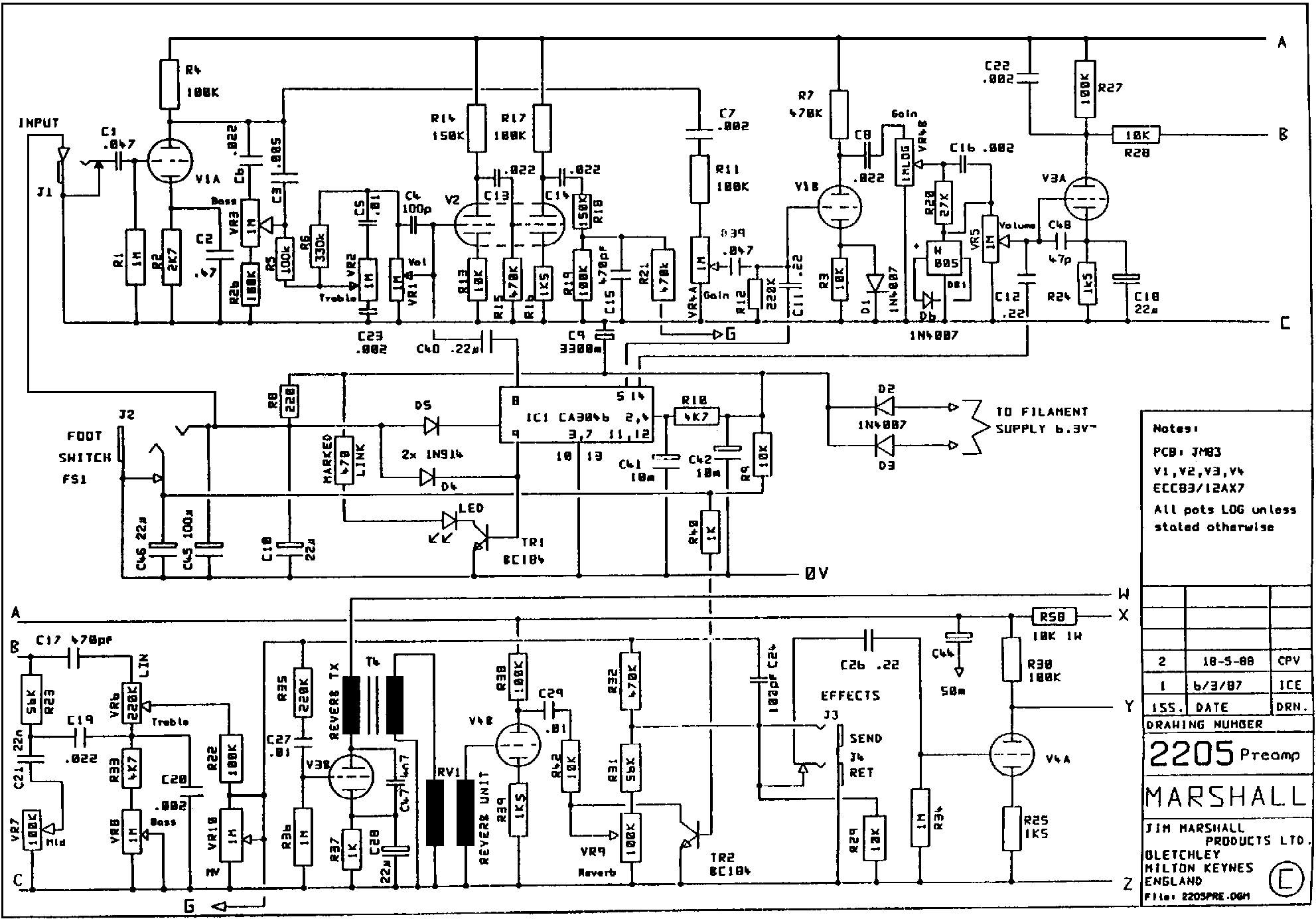
Now 1 more question, somewhat related:  I don't know what is meant by the connection from footswitch input jack tip, and what seems like possibly a switched shield on the amp input jack in marshall's 2205?
2205prem.gif
 
Interesting eq tone stack on the 2205,(lower left corner schematic ).  I never noticed the mid pot connected that way.  Similar to a Dumble or tweed fender.  I assumed  it was like 2203.  Learning something new.
 
fazer said:
Interesting eq tone stack on the 2205,(lower left corner schematic ).  I never noticed the mid pot connected that way.  Similar to a Dumble or tweed fender.  I assumed  it was like 2203.  Learning something new.
Yes, different implementation but identical results, excepting some deliberate changes, such as slightly shifting the midrange.
 
Back
Top