Hairball Audio: 1176 Stereo Linking PCBs Support Thread

GroupDIY Audio Forum

Help Support GroupDIY Audio Forum:

This site may earn a commission from merchant affiliate links, including eBay, Amazon, and others.

Echo North

Well-known member
Joined
Jan 21, 2006
Messages
4,452
Location
Seattle, WA
PCB_White.jpg

A few months ago I started thinking about offering a stereo link option for the 1176.  My initial thought was that the “Pad 7” (direct connect) method was not a great solution so I started down the path of offering a version of the 1176SA circuit.

I asked Ed Andreson if he had any advice on the topic and he shared an insightful analysis of the linking options.

----------
To get two 1176s tracking in stereo, you'd want the GR FETs on both to get the same DC signal.  So lets say we tie the point at the output of both sidechains together (Pad 7 meathod).  Now the outputs of the sidechains are in parallel.  A side effect is that now both the attack/release networks are also in parallel, which means the minimum attack time is doubled.  Another side effect is that the controls interact.  You can read about it in the manual, but it does make the settings a bit trickier.  If the FETs are perfectly matched, then the DC control voltage at zero compression should be the same on both units.  But what if they aren't the same?  Then there is a DC potential between the two FET control lines, and current will flow from one unit to the other, which is a problem.

If you look at the 1176SA adapter as shown in the urei 1176 manual, you can see that it is basically a battery and a pot.  This is the solution... the battery is a floating (not referenced to any power supply in either unit) voltage that you can stick in between the two FET control lines to bridge any difference in DC voltage, so that there is no current flow.  The pot allows you to adjust the voltage to exactly match the difference between the two units.  The problem with the "solution" (apart from the side effect of doubled min attack and control interactivity) is that while the FETs may be matched at no GR, it make take a different amount of DC to make each FET do, say 10db of gain reduction as an example.  You can trim those differences out in the meter circuit to make the meter FET track the GR FET, but you'd have to introduce a more complex adjustment to get the two GR FETs to track each other reliably over a wide range.  In the 1178 urei went with a matched FET pair chip, which is basically unavailable today.

The purple solution, which you can see on the MC77 schem, is to take the audio from the output of the first stage on each unit, buffer and sum it together, and then feed the summed audio to both sidechains. so the sidechains in both units hear the summed program material, and they don't have to really be paralleled, so there are no side-effects

----------

After considering Ed’s thoughts, I decided the best option would be to offer a project that utilized the Purple Audio summing option.  Purple Audio graciously gave me permission to offer the circuit and mnats kindly offered his PCB layout skills.

The 1176 stereo linking boards are offered as a kit or PCB’s only here:
http://hairballaudio.com/shop/product_info.php?cPath=22&products_id=50

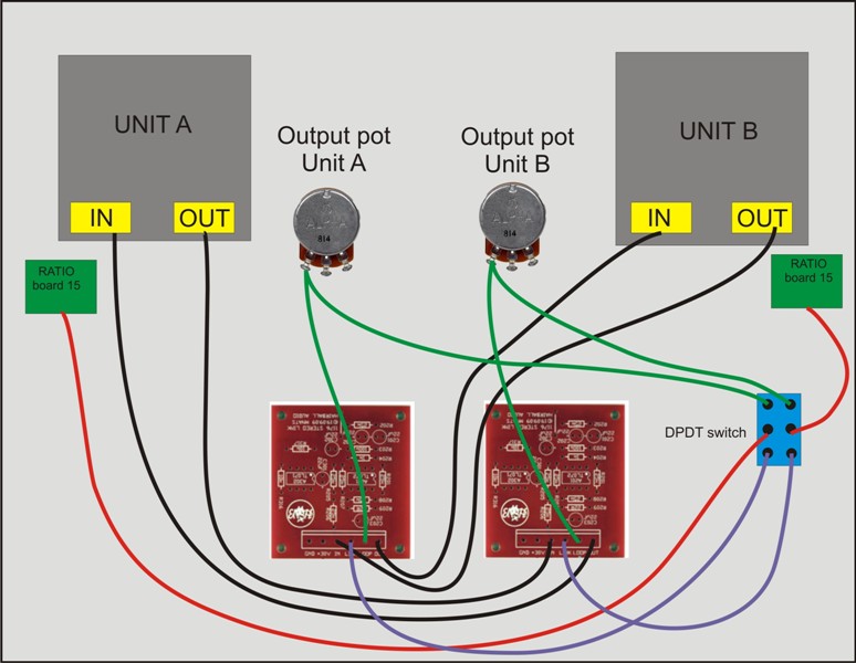
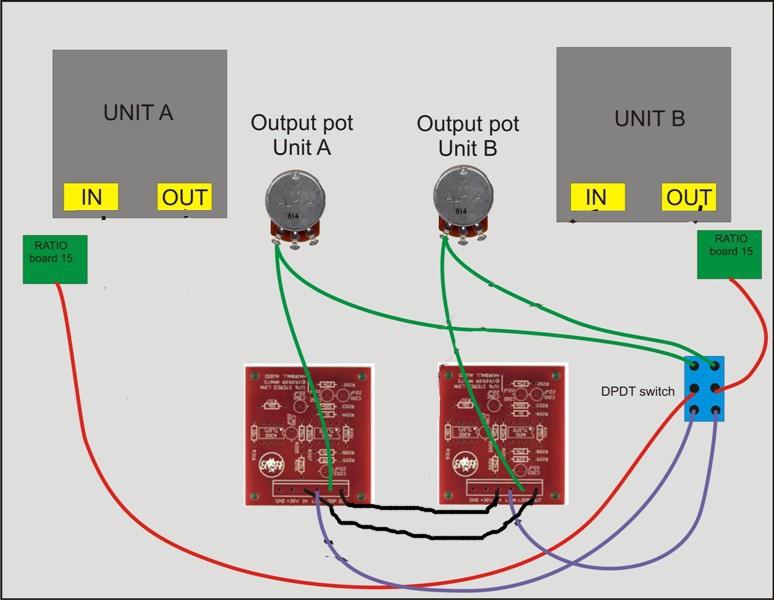
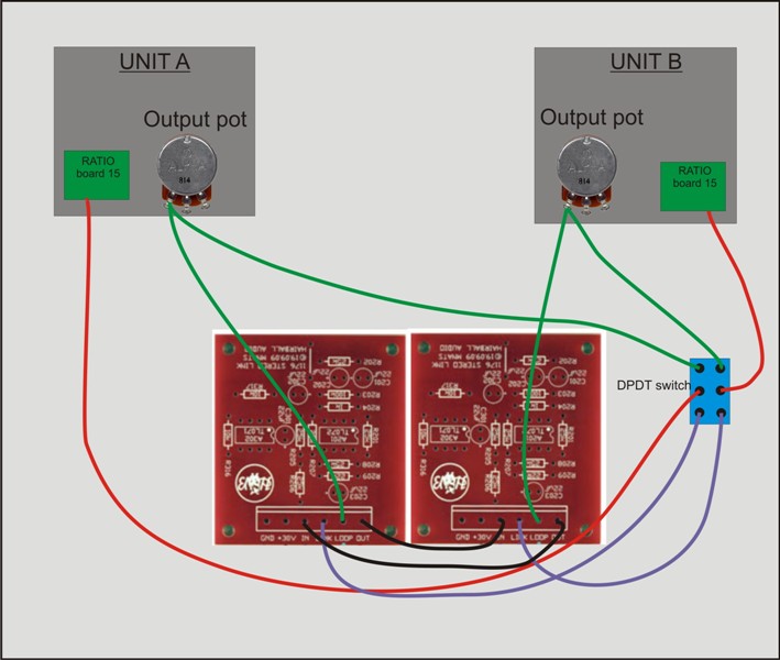
Two boards are required to link to units.  Wiring instructions can be found here:
http://library.hairballaudio.com/datasheets/Stereo_Link_Wiring_Guide.pdf

For proper stereo operation the units should use the came control settings and have reasonably matched GR FETs.  Hairball Audio only accepts FETs with curves within a specific range.  Any two pairs of matched FETs purchased through Hairball Audio should provide stereo linking within 1db up to 10db of gain reduction.

Support questions can be posted in this thread.
Ordering questions should be posted in the Hairball Audio White Market thread located here:

http://www.groupdiy.com/index.php?topic=28923.0

Thank you to mnats, Purple Audio and Ed Anderson.

Mike
Hairball Audio
 
Very cool mod board!

So for stereo 1176's built with stereo matched FET's from Hairball, do still recommend using this board?

Also, since you're summing the L/R image and sending that to both sidechains, are there any compression artifact issues caused by this?  Particularly with bass-heavy center panned tracks like kick and/or bass gtr?  I'm asking because the GSSL sums the L/R which can cause compression artifacts, and that was the reason the turbo board came about for that comp.
 
I must admit I'm not too familiar with the compression artifact issues in the GSSL.

Most of my testing involved the function of the PCB layout as the design itself has existed in a commercial product (MC77) for a while.  I have not personally heard of any issues with artifacts in the MC77.

My guess would be that if there were any issues it would be at high ratios with high amounts compression, but I'd have to research it more.  I may get a chance to ask the guys from Purple next weekend at AES. 

I think it's a great mod and it's really not that much more work then wiring the "pin 7" method.  I'm not offering stereo matched FETs anymore because they simple required way too much time.  This kit with an 2 sets of FETs I sell (or anything you reasonably match) will work a lot better and will cost less money.

If you do a lot of stereo compressing I would suggest this project.

Thanks!

Mike
 
What revs of the 1176 does this stereo link theory/kit apply to? I'm building the rev D.
Thanks
Dan
 
Hi all!

I suppose I can use this thread for next one.

I didn't notice in time of my order for trafos and etc. from Hairball there is stero link boards so I found self etch files from lovely Mr. Nats site.
I stuffed couple of boards today I noticed there is no holes and soldering taps for C301. In check plot they are so they are missing only in etch picture.
Not really a problem there's space enoght to drill couple of holes and bend cap legs over the track.

Obviosly refering to the picture in first message of thread there is these holes and taps in Hairball's boards.

All best,
Paavo
 
I've been holding off mentioning the page as it is still in draft form (though linked from my index page). I've fixed the files - thanks for pointing out the error.

Can't imagine that many people would choose to self-etch when the Hairball kit is so cheap but I think it is good DIY etiquette to allow those who prefer to etch at home to do so or who don't have the wherewithal to purchase from Hairball. Later I'll do some test results and some hook up explanations and/or photos as time allows...

Oh - here's the link to the new document: http://mnats.net/files/STLNK1.1DOC.pdf
 
I may have gone off the deep end trying to understand this 1176 circuit to make a well matched pair of 1176 revD compressors. I would say getting two units to work well with the stereo link is very difficult. Even building a matched mono set is difficult. I bought 10 FETs and matched the best 4 into pairs. Built the two units. Both work well, and calibrate correctly. First test is swap the two FETs in the individual 1176s to see how closely the GR meter matches the actual circuit GR. One 1176 is nearly perfect, one it about 2-3 dB off. Next test, hook up the stereo link. Two units, when fed the same signal, are not even close. about 4-5 dB off. The GR curves match very closely however (I posted the graphs in the rev D thread). The response of the FET to changes in voltage, however are significant. I think the FETs need to be matched VERY closely. Maybe I'll save up and order 100 from mouser. 
 
The FETs vary WIDELY.  It's actual very shocking.

I buy FETs 2000 at a time.  probably 60% end up in the rejected bin because they are way off the ideal curve. If you want 4 FETs matched within 5 or 10% and also have them close to an ideal curve you will need a lot more than 10 FETs.

I've started to get very tight with my matching tolerances.  The stereo link kit and 2 pairs of matched FETs from my store should get you within a dB.

If you're using the pin 7 method for linking, that is a whole different story.

Mike
 
Well, 2000 FETs would cost $260 at $0.13 a piece... but the loss of my sanity checking them would be even steeper ;)
I used the awesome Hairball stereo link kit, of course.
I actually thought the FETs matched very closely. I built the test jig described on this forum, and had  voltages 1.79/1.50, 1.81/1.54, 1.73/1.47, 1.78/1.51. The later two were the pair that showed the difference in one of the units.
Mine were probably way off the ideal curve because I needed a 5k trimmer to get the GR calibration to work.
 
Hi,

I am actually finishing the wiring of my dual 1176 rev J.
I would like to add the two Stereo link boards but, I do not know how  ???
I read the instructions, but I am not really sure...

I made a quick schematic
Is it the right wiring? :


stereo%20linking.jpg


thanks a lot
 
mathflan said:
Hi,

I am actually finishing the wiring of my dual 1176 rev J.
I would like to add the two Stereo link boards but, I do not know how  ???
I read the instructions, but I am not really sure...

I made a quick schematic
Is it the right wiring? :


stereo%20linking.jpg

Great diagram mate, would be helpful to newbies. It be good if you shows which pins on the in and outs the wiring goes to? Is that the XLR ins and outs for unit A and B?


thanks a lot
 
Looks good to me.  Give it a try!

canidoit "in" and "out" are not connected to the board they are connected to interconnects (rca...1/4 inch...).

Read here:
http://hairballaudio.com/guides/Stereo_Link_Wiring_Guide.pdf

mathflan if you have a dual unit you can just hard wire in to out and out to in.

Mike
 
Hello. Someone could help me with the wiring to a D version with rotary switches, I've tried several ways and it doesn't work.
Thanks
 
Back
Top