Help! adding regulator to a microphone power supply

GroupDIY Audio Forum

Help Support GroupDIY Audio Forum:

This site may earn a commission from merchant affiliate links, including eBay, Amazon, and others.

thekid777

Well-known member
Joined
Aug 1, 2009
Messages
455
Location
France
Hi,
I need to add a regulator in a power supply to protect the tube of the mic
I attached the schematic and would like to know if what I want to do is ok
I thought about removing R8 and put a 7805 (LM740) instead with a trimmer of 100 ohm
as I need to get 4V under load.
On the right of the schematic there's the value of the components
I find 20V at R7 without microphone connected
In the present state of the psu (unmodified) I get 4,1V under load (mic connected) but I really need to go down to 4V
and most of all to have some regulation!
Thanks a lot for your help!! ;)
 

Attachments

  • psu regulate.jpg
    psu regulate.jpg
    1.4 MB · Views: 50
An 7805 will give you 5 volts.
Adding a resistor or diode (to ground) will raise the output voltage.
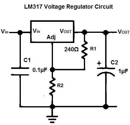
Personally I would use an LM317 here. (Adjustable 1,2-30 V)

LM317-schematic-diagram.PNG
 
I would leave that circuit alone, however I would use a variac to control the input AC voltage to the module to set the AC supply voltage to what it was designed for this could be why the heater can not go lower than 4.1VDC if I understand the first post.

Check R9 value(330 ohm 2watt? hard to read) if you ran this without a load

You have good regulation
Variable resistor before the diodes helps with soft starting, diode bridge, cap, inductor, cap, resistor, cap, resistor, cap, variable resistor(R9 looks like it is across the output to load the supply down before the relay switches to the tube heater)
ALSO note before the last resistor R9 another resistor R10 goes to a relay coil I am guessing for a time delay

Not sure why V1 and V2 are wired like that off the other set of contacts is V1 marked power on and V2 marked heater on?
Is transformer pin 4 to 2, 12 or so volts AC


Two reasons to leave it stock one it looks old and I would guess the modern AC voltage is higher than the voltage when the circuit was built and other parts might be running at higher voltages and current than when designed
another is 3 terminal regulators are not good for this application
 
Thanks guys!

Gus:
Make sense!! I think there was 220V at the time this power supply was running.
And know I have 230v!

I'm really after keeping it as original as possible as it worked fine but protect the costly ac701 is a must as well!

I never used a variac! that's easy to find?
From what I understand it is to  adjust input ac voltage but I'm not sure  it can regulate it
I looked some days ago for a furman regulator and filter which could give me 220 but didnt find anything

ps: yes V1 V2 is respectively power and heater (when mic is hooked up which has to be done before powering psu, if not tube will be shot as it output 20V unloaded)

Thanks!
Best regards
 
4.1/4.0 over-voltage will not significantly shorten the life of the heater.

Small audio tubes almost never fail due to heater burn-up.

Hot-plugging the heater supply is not a disaster. While it may rise to 20V no-load, the heater will pull it down very fast, about 0.1 seconds with these cap values. Even a thin heater won't hot-up much in 0.1 seconds.

Series resistance IS the best protection against starting surge. Lift one end of R8 and add 1 Ohm in series so you get your 4.0V.

Actually R6 variable is probably FOR trimming the loaded voltage, but I can't read this image. But I think if you slide/turn this 3% you get on your target.

220V to 230V is within the design allowance for heaters.
 
Indeed PRR thanks for your message
R6 pull down the voltage before diode bridge but I can't go lower than 4,1 adjusting it.
It seems ac701 are really fragile and sensitive unlike most other tubes and more than 4,2 would down lifetime  badly (from what I read from different microphone techs) I have been told a shot of 20v would destroy it immediatly!
Why adding one 7805 instead of R8 couldnt do it? What could be "problematic"?
5V unloaded could end at 4V mic connected
 
I was going to post about adding a resistor in series with the one before the diodes, however the rest of the circuit is getting more voltage as well.

I still think reducing the AC supply voltage is the best thing to do.
 
3 terminal regulators can add issues.

The person(s) that designed this power supply look like they knew what they were doing
The 2H inductor, capacitors and resistors used for the heater supply is a nice design

Some Variacs have a meter on them to read the supplied AC voltage.
 
thekid777 said:
Inside psu
Looking at your pictures, are the red and black wires on C-5 and C-6 getting pinched where they come through the chassis? It sort of looks that way, especially on C-5.

Just trying to help.

Gene
 

Attachments

  • C5 C6 wire pinch.jpg
    C5 C6 wire pinch.jpg
    40.5 KB · Views: 13
thekid777 said:
...I need to add a regulator in a power supply to protect the tube of the mic...
I thought about removing R8 and put a 7805 (LM740) instead with a trimmer of 100 ohm
as I need to get 4V under load....

If you like to insert a regulator, IMO you should change the values of series resistors R6 and R7 also, because regulators need more input voltage to work properly (cca 3 V). 

In the present state of the psu (unmodified) I get 4,1V under load (mic connected) but I really need to go down to 4V
and most of all to have some regulation!..

Did you get this voltage on the PS output or on the tube? The PS cable introduce some voltage loss, so if I remember correctly what I got on Neumann NKMa ,4,1V at PS gives 4,0 at the tube. The underheating of AC701 also isn't good for its lifetime.
 

Latest posts

Back
Top