Help understand this tube effects loop circuit

GroupDIY Audio Forum

Help Support GroupDIY Audio Forum:

This site may earn a commission from merchant affiliate links, including eBay, Amazon, and others.

isophase

Well-known member
Joined
Jul 2, 2007
Messages
240
Location
Lutece
Hello GDIY,

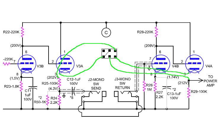
I’m trying to understand this tube effects loop circuit design from a Soldano super lead 60 amplifier.
Especially the return section where the signal inputs straight to the cathode of 1/2 12AX7 tube.
I never saw this type of montage before in a tube circuit.
I did search « cathode input tube preamp circuits » with no luck.

Questions:
-Is this common ? (Any other exemple circuits someone can share for reference?)
-Does this circuit have a name and what is it called?
-What happens when signal is fed direct to a cathode of a tube and out from the anode? Polarity? Gain?
-and if the grid was left unconnected ?

also, regarding the send/output section of tube effects loop circuits, I sometimes see both cathode follower and common cathode circuits. In which case/senario one would favor one over the other ?

effects loop circuit schematic attached for reference.

10742A45-7A0F-4E95-9C56-B8D62528935B.png
Thank you!
 
Ha!
Ok, thank you!
Still wondering though, is there a possibility for signal to enter from the cathode ? If it was not grounded of course, could the signal pass through?

How about common cathode vs cathode follower, is one better than the other in the context of an fx loop? For example if someone would feed a pedal or a line input?

sorry in advance for very « basic » questions
Thank you
 
Even without the obvious errors on the return amp, that looks to be a poorly designed FX loop. Likely, it is not very transparent.
 
An effects loop has two considerations: for sending, you need to be able to drive a reasonable collection of outboard gear at a reasonable level. If you plan around +4 dBu, this implies a drive of about 2V peak into 600 ohms worst case. You might also want a switch or pot to drive effects expecting -10 dBv.

This implies a low output impedance capable of swinging 2V into 600 Ohms (which should be is the wort case).

For return, you want to be able to drive the power amp to full output power when your outboard gear is putting out a reasonable level. If the phase inverter needs about 5V peak, worst case is -10 dBv which implies a gain of about 10. Many effects returns plan for 20dB of optional gain at the return, with a high input impedance.

That circuit fails at both goals, having a high impedance send and marginal gain recovery, and no gain adjustability to handle different signal levels dynamically.
 
Thank you gentlemen.
I was reading a few articles on basic tube circuits/topology yesterday and did some “catch up”. Specially common grid circuits which I didn’t know about…
I’m also looking at different tube effects loop circuits because I have this idea about a stereo tube “instrument” preamp that I would like to try out with effects loop implemented. I don’t have the skills to design a preamp from scratch so I will copy bits and pieces from different designs and try to come up with a schematic base.
I will do a new thread with schematic soon. And of course I will need your help and advise again! :)
Till soon,
Jonathan
 
An effects loop has two considerations: for sending, you need to be able to drive a reasonable collection of outboard gear at a reasonable level. If you plan around +4 dBu, this implies a drive of about 2V peak into 600 ohms worst case.
No one in their right mind expects a guitar amp FX loop to be capable of driving a 600r load. A typical pedal has an input Z of 100k, and some multi-FX processors have an input Z of 10k.

For return, you want to be able to drive the power amp to full output power when your outboard gear is putting out a reasonable level. If the phase inverter needs about 5V peak, worst case is -10 dBv which implies a gain of about 10. Many effects returns plan for 20dB of optional gain at the return, with a high input impedance.
Since there is a major cock-up in the schemo, you don't know the gain of V3a, but it's quite possible the anode res is also 100k, same as V2b, so there is plenty of gain here (about 30dB)
That circuit fails at both goals, having a high impedance send and marginal gain recover and no gain adjustability to handle different signal levels dynamically.
I don't agree regarding the two first points; regarding the adjustability, the designer is relying on the pedal's capabilities to perform the necessary adjustments.
Mike Soldano is a respected guitar amp designer; I would trust him to know what he does.
 
No one in their right mind expects a guitar amp FX loop to be capable of driving a 600r load. A typical pedal has an input Z of 100k, and some multi-FX processors have an input Z of 10k.
If you aren't interested in using old gear (like 1176, LA2A, or Pultec EQ's) in the loop then I agree. Much like their personal relationships, guitar players tend to stick everything they own into everything else.

Here's a correct version of a Soldano effects loop:

loopbypassswitch_1_by_haftelm-d7kok2b.jpg


And a few others if you don't want to blow two dual-triodes just to have a loop in your amp:

index.php


Or any triodes at all:

index.php
 
Here's a correct version of a Soldano effects loop:

loopbypassswitch_1_by_haftelm-d7kok2b.jpg


And a few others if you don't want to blow two dual-triodes just to have a loop in your amp:

That is not much better (and I wouldn't do the switching like that). Neither this one or the OP will do 2V into 600 ohms if that's your concern. And the impedance seen by pedals and gear is not that much different either, around 2k vs 4.5k.

Often a loop will use one additional tube What's nice about the OP version is that it doesn't, all it needs is the receiving triode which would have been an unused 1/2 tube anyway. (The receiving triode is drawn wrong as others have pointed out.)
 
It’s worth mentioning that this particular loop design (the Soldano) provides a rather integral shaping of the sound that shouldn’t be dismissed if making a clone and perhaps avoided if looking for a good “drop in” loop schematic. The DC coupled cathode follower at the end of most Marshall preamps (found here and in the Mesa Rectifier series as well) draws some current at its grid in positive swings. It adds some compression, 2nd harmonic distortion, and smooths out the harder clipping of an earlier cold clipping stage. The SLO has a second DC coupled follower after the loop make up gain. Assuming nothing in the loop inverts phase (the make up stage will) this all means that both sides of the wave form gets this treatment. To my knowledge this is unique to Soldano amps.

Most other loop designs are “tacked on” to the end of the preamp as a way to facilitate routing; in the SLO it is integral to the preamp itself. I wouldn’t use this design if the goal was transparency.
 

Latest posts

Back
Top