Help understanding schematic I traced from point to point wired, mystery tube device labeled “non-linear amplifier.”

GroupDIY Audio Forum

Help Support GroupDIY Audio Forum:

This site may earn a commission from merchant affiliate links, including eBay, Amazon, and others.

AardvarkBry

Tinkerer who doesn’t know nearly enough to fiddle
Joined
Apr 30, 2020
Messages
83
Location
Ossining
I posted on here a while back if anyone knew any information about an old Naval tube amp labeled “non-linear amplifier.” The consensus seemed to be it was some sort of limiter. I finally got around to tracing the circuit, and did my best to write a schematic based off what I traced. It appears to my not super well trained eye, to be an ordinary microphone tube preamp, with a cathode follower output. What do you guys think?

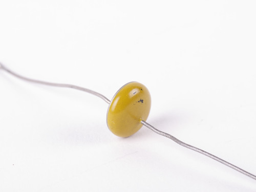
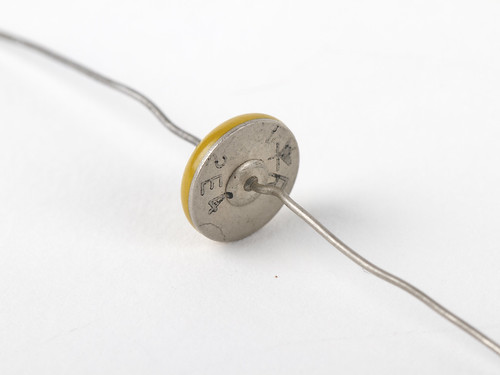
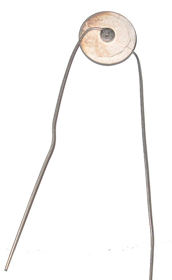
It’s 3 stages of 6SJ7s and a 6V6 for the cathode follower output. I’m sure the way I notated the 3 10uf/10uf can caps feeding B+ to all the plates and grids, is not super correct. I wrote “disc,” for the mystery flying saucer component.

A few puzzling things I don’t quite understand:

1. There are the strange tiny flying saucer discs, probably ceramic, I’ve never seen before. I assume they’re ceramic caps? I included a picture.
2. What are the points of the trim pots going into each preamp section?
3. I assume the way the plates and grids get their B+ is probably pretty normal, but don’t understand how it all connects. It’s all kind of one big loop from the input to output, with each preamp section having an additional feed. Is this some sort of negative feedback system?
 

Attachments

  • 04B805ED-7C1F-4AB9-913E-045E313967E1.jpeg
    04B805ED-7C1F-4AB9-913E-045E313967E1.jpeg
    870.3 KB · Views: 8
  • 09296B9D-2DE4-4B82-9E1C-5D3FA3C75C0F.jpeg
    09296B9D-2DE4-4B82-9E1C-5D3FA3C75C0F.jpeg
    717.4 KB · Views: 3
Here’s the device, if this helps anyone.
 

Attachments

  • 259DB220-681F-48FD-9036-2E42C3CC38F4.jpeg
    259DB220-681F-48FD-9036-2E42C3CC38F4.jpeg
    3.5 MB · Views: 5
  • 2025158A-6203-4933-BAD8-E16BF6BCC6C7.jpeg
    2025158A-6203-4933-BAD8-E16BF6BCC6C7.jpeg
    625.3 KB · Views: 2
  • 29A270F3-514A-4280-9A73-E11AB6ED5E1F.jpeg
    29A270F3-514A-4280-9A73-E11AB6ED5E1F.jpeg
    3.4 MB · Views: 3
Last edited:
Interesting unit, this is the first time I've seen a 6V6 in triode operation as a cathode follower in an amp.

1. I also believe that the flying saucers are ceramic capacitors. I suspect they form a variable bandpass with the trimmers, which is mentioned on the front panel.

2. as said, they could be the variable part of the filter.

3. I am not sure if this was traced and drawn correctly. Somehow it's weird and hard to understand at least for me. I think this is supposed to be the NFB, since 3 pentode stages in a row without NFB tend to be unstable. As it is drawn, I don't recognize the NFB loop atm, but only a double, unnecessary B+ supply for V1, right?

All just conjecture, just my 0,02$ at 6 am.

Edit: one of the two gain pots is missing in your schematic.
I think you’re right about the outer top loop. I drew out a quick sketch of the B+ rails by themselves, and looking at this sketch, I think I overthought it. I got confused because there are jumpers connecting every stage to each other. The output stage connects to a central hub, which feeds each stage. You are also correct, I forgot to include the first input volume pot. It’s directly after the input transformer, and feeds the pin 4 of the first 6SJ7. Also, I just noticed those 2 saucers in series at the output, connect to the cathode, not the plate. I had a brain fart. All the 6SJ7s, pin 8 is the plate, but 6V6 8 is the cathode. Had a senior moment there drawing out the diagram. The cathode does still feed the output transformer though.
 

Attachments

  • F3E6AB37-C116-46D4-BF93-DD32BA8FB538.jpeg
    F3E6AB37-C116-46D4-BF93-DD32BA8FB538.jpeg
    2.2 MB · Views: 1
After going over this for hours, here’s a revised schematic I came up with. Not a whole lot different.

1. I got rid of the unnecessary top B+ loop
2. The output stage mystery saucers go to ground rather than the plate.
3. Added the input volume pot
4. I noticed that the negative B+ leg connects strait to the heater pin 7 of the 6V6. Is that so the heater line has a high voltage ground reference?
5. Added the power switch
6. Added the feed to the phones jack before the output stage.
7. I noticed everything is on the same ground bus, except the mystery saucers before the 3rd stage. They are the only thing with their own, independent chassis ground.

The myster saucers all have a numbered tag taped to them. They’re the only components with this tag.

Another odd thing I noticed, is all the trim pots, are located in a place that puts them inside the metal box, the amp gets bolted to and housed inside. So if they’re for band pass, it’s a major pain in the rear, because you would have to disconnect the power supply, unbolt the chassis, and remove it from the metal box to adjust them. They’re definitely for “set it, and forget it” purposes.

I don’t have the power supply that belonged to this device. I have a lambda regulated power supply, but it only goes down to around 200 volts. The supply hook up jacks on the back say “180v B+.” The high volt caps are all rated for 450v. The cathode bypass caps are only rated for 25V. 6SJ7 is rated for 300v max plates, and 125v max screen grid. Will 200 volts be ok, or should I drop it down to 180 with a resistor?
 

Attachments

  • 52D2E6D8-14F6-43A7-A675-14D79BAC42E1.jpeg
    52D2E6D8-14F6-43A7-A675-14D79BAC42E1.jpeg
    2.4 MB · Views: 4
Thermistors?
Isn't it the basic function for a THERMally-sensitive resISTOR to have resistance? :cool:

I checked for resistance, and it measures 0 across them, every way I measured. That’s with the unit is not powered up
But zero resistance is also untypical for a capacitor, strange.

I'll have to take a closer look at your new schematic. Strange device, but certainly a good basis for a fat mic preamp. Somewhat similar to the old RCA and Gates units. Does the thing work, how does it sound?
 
Last edited:
Thermistors?
To me the discs look more like they could be thermistors or varistors or perhaps even a diode. I've seen plenty of old disc capacitors and none of them have looked like that, but you never know.

Couple old time diodes
7579231108_1c09e969f5.jpg

7579246828_2de156b524.jpg


Thermistor
THERMISTOR%20100%20OHM%20NOS.JPG
 

Attachments

  • varistor.png
    varistor.png
    67.4 KB · Views: 1
Last edited:
Yes, it could be a diode, but the question remains, what sense does that make in the circuit? How do you achieve a bandpass with it?
Anyway, I would bypass this stuff or throw it out and build a nice mic pre with it.

Just as a rough idea, this classic...
RcaOP-6Schematic.jpg
3x Pentode amplifier stages are a ton of gain, probably too much in the modern studio. But there are other american vintage mic pres that can be used as a role model.

I think the bandwidth of the transformer is very important, if it can get anywhere near full audio spectrum it will be a great amp.
 
Last edited:
Two doides in parallell to ground seems reasonable as a nonlinear/clipping funktion.

If you have a variabel voltage source and one/two multimeters you can do a little investgation and plot a V/I diagram.

They May be non functionable aswell...
 
When current rises, impedans go low making The hipass f_o go up.
f_o = 200 Hz gives with C = 0.02uF an impedance of about 40k. Which i think is pretty much a short in the circuit.
 
My guess is varistors, which change resistance with voltage. That will make it non linear for sure.
Also you have no grid leak resistor to ground from the control grid of the second tube. Another 470K which seems to be popular?

Something should be there. Do you have a scope? That will tell you a lot.

Whatever that is used for it appears to have a lot of gain with 3 pentodes in a row.
 
To me the discs look more like they could be thermistors or varistors or perhaps even a diode. I've seen plenty of old disc capacitors and none of them have looked like that, but you never know.

Couple old time diodes
7579231108_1c09e969f5.jpg

7579246828_2de156b524.jpg


Thermistor
THERMISTOR%20100%20OHM%20NOS.JPG
I thought varistor too, but I wasn’t sure whether or not they would measure a resistance. The only circuit I’ve ever seen them in, were the old Magnetone amps, where they used them to make the tremolo. Maybe this could be some very early diode clipper limiter?
 
Yes, it could be a diode, but the question remains, what sense does that make in the circuit? How do you achieve a bandpass with it?
Anyway, I would bypass this stuff or throw it out and build a nice mic pre with it.

Just as a rough idea, this classic...
View attachment 100747
3x Pentode amplifier stages are a ton of gain, probably too much in the modern studio. But there are other american vintage mic pres that can be used as a role model.

I think the bandwidth of the transformer is very important, if it can get anywhere near full audio spectrum it will be a great amp.
I’m like 90% sure the output transformer is a Peerless. There’s no label, but it looks exactly like one. It’s got the exact same casing. I’m not sure what the impedance is though? I don’t know much about cathode followers. I’m very confused by them. They have a very low impedance output, like 400ohms, but they want to see like 100k? The input transformer is a very nice looking 600:50k Hollytran.
 
Two doides in parallell to ground seems reasonable as a nonlinear/clipping funktion.

If you have a variabel voltage source and one/two multimeters you can do a little investgation and plot a V/I diagram.

They May be non functionable aswell...
I have a Variac, but only 1 multi meter.
 

Latest posts

Back
Top