High Pass Filter for Neve 1272 / 1290

GroupDIY Audio Forum

Help Support GroupDIY Audio Forum:

This site may earn a commission from merchant affiliate links, including eBay, Amazon, and others.

earthsled

Well-known member
Joined
Dec 1, 2009
Messages
405
Location
Asheville, NC USA
Hi all.

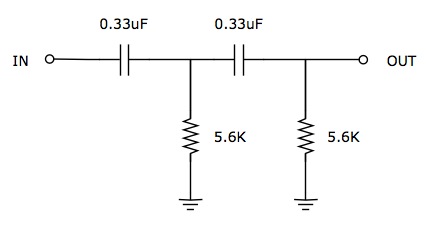
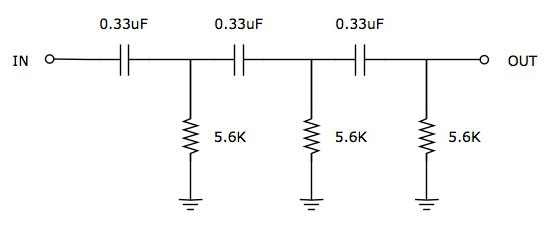
I'd like to add a HPF to a neve-like 1272 / 1290 preamp similar to this: http://www.jlmaudio.com/JLM1272hotrodmod.pdf. I understand that it's possible to simply add a small value cap between the input and output sections of the BA283 board (between pins P and L).

My questions are: What value cap should I use? Is there a way to calculate for an 80Hz cutoff vs. 100Hz? Also, does the 5.6K resistor (in the JLM circuit) need to change value for the HPF?

Thanks in advance for you help!


Hey,

... I'm not an expert but I guess more values on output & input impedances of points P & L would be needed as well as information on what is inside the "note1" box (unless I miss-read the schematic and this information is there).

Best regards,

Jesper
 
Hi Jesper,

I wish I knew the impedance values. You are right, these values are probably needed to calculate the proper cutoff for the HPF. Hopefully somebody on this forum is familiar with the BA283 / BA183 boards and would know the impedances of each section.

As for the schematic - if you look below you'll see that there are 3 different options for "Note 1". I'm planning to use the fixed resistance or "Ver. A".

-Seth

 
earthsled said:
Hi Jesper,

I wish I knew the impedance values. You are right, these values are probably needed to calculate the proper cutoff for the HPF. Hopefully somebody on this forum is familiar with the BA283 / BA183 boards and would know the impedances of each section.

As for the schematic - if you look below you'll see that there are 3 different options for "Note 1". I'm planning to use the fixed resistance or "Ver. A".

-Seth
Then you need to insert a cap before the fixed resistor. The fixed resistor is dominant in the input impedance. The value of the cap is given by the equation C = 1/2pi.f.R. For 80Hz, that would be 330nF (0.33uF).
 
Wow. Is it just that simple?

hpf.gif


math_image.aspx


Great information! Thank you!


..1st order, that is..you get only a 6 db/octave slope.
The original is 18 db/octave.
Cheers Bo
 
Just look at the orginal schem. You need two 0.47 caps and a 7H inductor to get a 80Hz cutoff. 5K load resistor.
 
It mght be worth looking into 3rd order / Butterworth filters in order to see how this actually works. It'll save any mistakes with your own design, and it'll then only take a few minutes of thought to figure out a similar filter next time.

There's a Wikipedia page, but it focuses mainly on a LPF example, which despite being very similar, I thought might confuse potentially. There is a nice audio filter design website somewhere, but I can't seem to locate it just now.

Roddy
 
Just look at the orginal schem. You need two 0.47 caps and a 7H inductor to get a 80Hz cutoff. 5K load resistor.

This is interesting to consider. The original 1073 design used a T1295 inductor to facilitate a multi-position high-pass filter switch. The T1295 was a 10H inductor tapped for 7H, 3H and 1.3H.

Mouser sells a 7H fixed power inductor made by Triad (model C-8X) for around $10 US, but I'm not sure if it would be appropriate for an audio circuit.

For my purposes, a single frequency high pass is all that's really necessary. Although, having a rolloff that is steeper than 6dB per octave is appealing.

Is there a way to increase the slope of a passive filter without the addition of a bulky and costly inductor? Perhaps a 2nd order filter would be a good compromise?

Thanks for your ideas everyone!

 
earthsled said:
Is there a way to increase the slope of a passive filter without the addition of a bulky and costly inductor? Perhaps a 2nd order filter would be a good compromise?

You can make a simple 2nd order filter simply by placing two 1st order filters in series. It is not perfect because the filters are not isolated from each other so in fact you get a pair of 6dB/octave filters working at slightly different frequencies but the ultimate slope is still 12dB/octave which is what you want. Many mixers use this simple technique.

Cheers

Ian
 
You can make a simple 2nd order filter simply by placing two 1st order filters in series. It is not perfect because the filters are not isolated from each other so in fact you get a pair of 6dB/octave filters working at slightly different frequencies but the ultimate slope is still 12dB/octave which is what you want. Many mixers use this simple technique.

Interesting. So I would use the same values and simply repeat the filter in series like this...?

HPF.jpg


Based on this idea, would it be reasonable to link 3 first-order filters together in series for an 18dB per octave slope? Are there adverse effects to setting up filters in series like this?

Thanks!

 
The only problem with that is that the response is overdamped, that means that ultimately the response is 18dB/octave, but the transition is not as sharp and the attenuation at the corner frequency will be higher than expected. See attached comparison of 3rd-order maximally-flat (Butterworth) and yours (overdamped).
Another problem with your proposal is that above 150Hz, it loads the output of the preceding stage with less than 2kohms, which it may not like.
 

Attachments

  • 3rd order normal & overdamp.jpg
    3rd order normal & overdamp.jpg
    74.2 KB
The only problem with that is that the response is overdamped, that means that ultimately the response is 18dB/octave, but the transition is not as sharp and the attenuation at the corner frequency will be higher than expected. See attached comparison of 3rd-order maximally-flat (Butterworth) and yours (overdamped).
Another problem with your proposal is that above 150Hz, it loads the output of the preceding stage with less than 2kohms, which it may not like.

I think the overdamped response curve is an acceptable compromise, but you have me worried about under-loading the previous stage above 150Hz. Could this potentially ruin the preamp's frequency response above 150Hz? Would I be better off with a 12dB per octave overdamped filter?

Thanks for your comments, this is a great help!

 
earthsled said:
The only problem with that is that the response is overdamped, that means that ultimately the response is 18dB/octave, but the transition is not as sharp and the attenuation at the corner frequency will be higher than expected. See attached comparison of 3rd-order maximally-flat (Butterworth) and yours (overdamped).
Another problem with your proposal is that above 150Hz, it loads the output of the preceding stage with less than 2kohms, which it may not like.

I think the overdamped response curve is an acceptable compromise, but you have me worried about under-loading the previous stage above 150Hz. Could this potentially ruin the preamp's frequency response above 150Hz? Would I be better off with a 12dB per octave overdamped filter?

Thanks for your comments, this is a great help!
The risk is making the previous stage work too hard, with decreased headroom and increased THD as consequences. The output of the first stage is pure classA with a 2k2 resistor. I consider anything under 6kohms compromises seriously the performance.
OTOH, you don't really need to use these low resistor values. You could multiply them by a factor 3 and divide the caps accordingly. That would make 100nF and 18k. The actual load above 150Hz would be 6k.
 
OTOH, you don't really need to use these low resistor values. You could multiply them by a factor 3 and divide the caps accordingly. That would make 100nF and 18k. The actual load above 150Hz would be 6k.

This seems like the best solution so far... Although, looking back at the graph, it appears that the overdamped filter will produce -6dB at around 250Hz. I wonder if it would be best to reduce my target frequency in order to achieve -6dB at 100Hz. How would I calculate this offset?

Also, out of curiosity, is there a different way to create a passive filter that would be closer to the maximally-flat curve, but without adding large inductors?

 
earthsled said:
OTOH, you don't really need to use these low resistor values. You could multiply them by a factor 3 and divide the caps accordingly. That would make 100nF and 18k. The actual load above 150Hz would be 6k.

This seems like the best solution so far... Although, looking back at the graph, it appears that the overdamped filter will produce -6dB at around 250Hz. I wonder if it would be best to reduce my target frequency in order to achieve -6dB at 100Hz. How would I calculate this offset?
Easy. Multiply the RC factor by the inverse of the frequency ratio.
100/250 = 0.4 1/0.4 =2.5  We know we can't very much deviate from 18k for the res, so we modify the caps.
100n * 2.5 = 250nF
So you can use 220nF and increase the R's to 20k.
Also, out of curiosity, is there a different way to create a passive filter that would be closer to the maximally-flat curve, but without adding large inductors?
I'm afraid not. Although there are ways of scaling the RC stage in order to make the response less damped (à la API), there is no way to make a passive RC filter resonate, which is what is needed for the task.
 
Easy. Multiply the RC factor by the inverse of the frequency ratio.
100/250 = 0.4 1/0.4 =2.5  We know we can't very much deviate from 18k for the res, so we modify the caps.
100n * 2.5 = 250nF
So you can use 220nF and increase the R's to 20k

Great!

Is there an equation I can use to plot the frequency response of the overdamped filter?

Thank you.

 
Back
Top