I've seen a few where they forgo the input transformer. I would think this somewhat defeats the purpose of having a high Z input on the preamp. So, is there a way to have a DI input in a preamp circuit without bypassing the input transformer?
You are using an out of date browser. It may not display this or other websites correctly.
You should upgrade or use an alternative browser.
You should upgrade or use an alternative browser.
How are DI's on preamp boxes usually done?
- Thread starter Ethan
- Start date
Help Support GroupDIY Audio Forum:
This site may earn a commission from merchant affiliate
links, including eBay, Amazon, and others.
MikoKensington
Well-known member
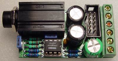
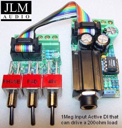
How about JLM's new gizmo?
deveng
Well-known member
The impedance of op-amp inputs are quite high. If your gain stage is configured as non inverting you can simply switch out the transformer, switch in a 10-100K resistor tied between the non-inverting input and ground. It's also beneficial to switch in a series resistance at about 3 times resistor mentioned above to pad down hot signals (approx. 12dB). The impedance seen by the line device or instrument would then essentially be the combined values of the resistor network tied to the non-inverting input. Adding the pad will stilll allow you to use the gain of the opamp if you pefer the color it adds (as would be the case of a 2520). Also, you would need to add a coupling cap as well. I've done this very thing before and it works very well.
An inverting amp configuration would be a bit more difficult.......and now that I've re-read your question........to keep the transformer (if it's a mic transformer) as far as I see it, would not work very well!
Regards,
Jeff
An inverting amp configuration would be a bit more difficult.......and now that I've re-read your question........to keep the transformer (if it's a mic transformer) as far as I see it, would not work very well!
Regards,
Jeff
blakbeltjonez
Well-known member
i was just wondering the same thing as i've been looking at doing a DIY version of the A*P*I 312...... from what i've seen there's no use of a transformer for D.I. - was wondering if the real 312/512's did this too or does A*P*I use the input transformer (or another transformer for hi Z inputs)?

$14.99
$16.98
Gikfun Upgraded USB Mini Amplifier Electronic Transparent Stereo Speaker Box Sound Amplifier DIY Kit for Arduino EK1918
Gikfun_Official_Store
pstamler
Well-known member
Given that most of the things you'd want to plug into an instrument input are unbalanced to begin with, I'm not sure there'd be much to gain by going through a transformer unless you want to add its coloration to the sound of your instrument. If that's the case, then going through a typical DI and reducing the signal to mic level, then going through the mic input on the preamp, would seem like the way to go.
Peace,
Paul
Peace,
Paul
I have found that plugging a guitar directly into a 2520 is amazing. Beyond that specific applicaiton, I like active DI's, which is what you need if you want to incorporate the input transformer. MOST of the "DI" inputs on boxes out there are simply 1/4" jacks that tap some part of a circuti that was never designed as a DI at all. the Brent Averill rack jobs are the worst offenders with this, as they use switching jacks that require coax run from the input transformer to the jack so not only is the "DI" worthless, but it kills the high end of the pre by adding a bunch of extra capacitence to the input which was never spec'd by the original designer. Averill is not the only company doing this... If you want a "real di" you should be thinking about an active solution in all cases, let alone if you want to use the input transformer. Plugging directly into a 325 line amp has worked for me in the past and also plugging directly into a quad eight opamp has had selected decent results but it all ultimately comes down to how the opamp and the instrument you are plugging into it play together. I would think if you wanted to run through the transformer, all that would go out the window and youd need an active input, which is probably the right way to do it in the first place. Dan kennedy's DI circuit is really nice for basses and guitars.
dave
dave
Funny you mention the Brent Averill method Dave. I was just browsing around the 1061's wondering why the DI sounded so bad in them and saw that same method you described here as what they had done for the DI. They cut a trace where the tx out to the circuit is and ran that out to a SPST switch and back. I'm glad I'm not the only one who found that odd.
Brian
Brian
clintrubber
Well-known member
So, is there a way to have a DI input in a preamp circuit without bypassing the input transformer?
There was (1) the circuit from Dan K at the old place, there's (2) the Jensen-circuit http://www.jensentransformers.com/as/as004.pdf which uses in essence the same topology and (3) Fabio has added a buffer stage on his 1272 mobo.
As I understood it all aim at keeping input-TX-colouring on purpose.
Bye,
Peter
JLM Audio
Well-known member
The New JLM Active DI Kit just cuts into the Cable coming from the Mic Input XLR that goes to the input transformer primary on any mic pre. It only needs one +12v to + 48v power rail to run on. It uses the two opamps from a OPA2604 in Parallel so it can drive 200ohm loads. It has a 1Meg input impedance on the jack so the loading to the guitar pickup is the same as a Fender or Marshall Amp. Inserting the jack cuts off the mic input and sends the active DI into the input transformer. By changing the IC to a TL062 the DI can be used as an external Active DI that will run from phantom power.

The IDC connector is only used if using it with our Go Between PCB which has 48v, 20dB Pad & Phase switches on it with a matching IDC on it. When the Go Between PCB is used the cut into cable is wired to the Go between PCB instead and only the IDC cable is needed to add the DI at any time.
These two PCB's are designed to make it quick and easy for anyone to convert API, Quad8, etc amp cards to have full mic pre functions.

The JLM Active DI Kit is $35AUD + GST or $28USD.
The JLM Go Between Kit is $24AUD + GST or $19USD.
When bought together we include the IDC cable and two end plugs as parts or made up ready to go if you give us the length you need.
Joe
www.jlmaudio.com

The IDC connector is only used if using it with our Go Between PCB which has 48v, 20dB Pad & Phase switches on it with a matching IDC on it. When the Go Between PCB is used the cut into cable is wired to the Go between PCB instead and only the IDC cable is needed to add the DI at any time.
These two PCB's are designed to make it quick and easy for anyone to convert API, Quad8, etc amp cards to have full mic pre functions.

The JLM Active DI Kit is $35AUD + GST or $28USD.
The JLM Go Between Kit is $24AUD + GST or $19USD.
When bought together we include the IDC cable and two end plugs as parts or made up ready to go if you give us the length you need.
Joe
www.jlmaudio.com
clintrubber
Well-known member
from Joe:
Bye,
Peter
That's important. So oops, I forgot to add that I'm using the Jensen-circuit I mentioned above with increased biasing (replaced R9-1k2 with a 'rich' current sink - I'm not using that circuit with phantom anyway).It uses the two opamps from a OPA2604 in Parallel so it can drive 200ohm loads.
Bye,
Peter
Similar threads
- Replies
- 5
- Views
- 369
- Replies
- 5
- Views
- 916


