I could use some help with this simple tube pre

GroupDIY Audio Forum

Help Support GroupDIY Audio Forum:

This site may earn a commission from merchant affiliate links, including eBay, Amazon, and others.

doulos30

Member
Joined
Jul 3, 2013
Messages
5
I'm trying to build a one bottle style mic pre. what I have is a tube power supply kit built. 6.3v dc heaters 350v regulated dc plate.  I have a separate 120 to 12v 300ma supply running into a regulated trippler lm317 style phantom circuit and a jlm audio go between kit and 2 transformers edcor xsk 10k/600ohm and a cinemag cm2511. 

the issue I'm having is almost all the circuits I have found have a much lower plate voltage the closest being 300v. ny dave 1 bottle. I tried loading the output with a restive load  44k at 5 watts to see if it drops but it doesn't so here I am.

my math with the 2 resistors i had on hand was 44k at 350v 2.8watt = about 8ma of current.
current draw across load is only 8ma of the 100ma load of the transformers max was my load just to small to see a significent drop? 

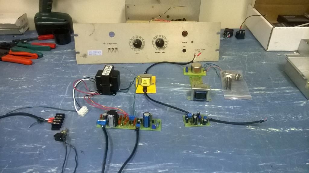
power supply kit and the parts I have
WP_20140620_008_zps6eeba16d.jpg


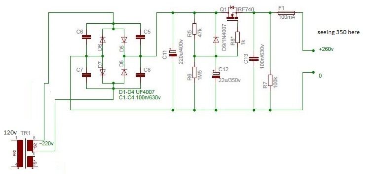
power supply section is here second tap goes to the 6v heaters.
psuedit2_zps23bbc3c7.jpg


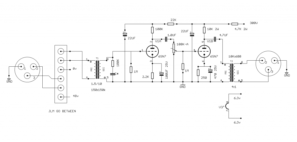
circuit I'm interested in
12ax7_zpse6c528f6.jpg


or is there a better circuit I can use to make a pre that has about 60db max gain with what I have?

any help and more importantly references to material I can read, so I can actually understand what is going on to adjust the plate voltage would be awesome. 
 
Most tube amps (not power-amps already on the ragged edge of melting) are VERY tolerant of supply voltage. 200V, 250V, 300V, 350V..... Fender runs tubes like your example with B+ nearly 390V.

Also: all class-A stages can use a Dropping Resistor and bypass cap. Try 10K and 40uFd and see where you get. Note that this also adds buzz filtering (so you really should not need sand in the power supply filter).

Nevertheless, you *should* know how to trim the voltage. Does this help?
 

Attachments

  • doulos30.gif
    doulos30.gif
    9.4 KB · Views: 78
That is what I figured I could do adjust R5, but its just such high voltage I wanted to make sure before I messed with anything.

changed the resistor to 680k and now im seeing 250v!!!! thank you
 
doulos30
Please check that Real McTube/Tomato etc are guitar preamps, I've noticed phantom and input trafo, well I'm not sure about using the schema with mic...

Take a look at good datasheet for ECC83/12AX7 (attached) - it describes how to use various supply voltages with 12ax7 in a cascade with plate load.

What about getting 140v out of 300v, I'd better took another trafo with secondaries suitable for the project.
 

Attachments

  • ecc83.pdf
    174.9 KB · Views: 7
As others have said, simple class A tube circuits are remarkably tolerant of HT voltage. If you decide to adjust it as others have described you need to be aware that the excess voltage is dropped across the RF470 and hence its dissipation will rise. You need to make sure it has an adequate heatsink. The reason you got 350V initially is simply because the supply was unloaded. As it is not regulated it will drop as soon as you load it. So be aware that if you set it to 250V unloaded, it will still drop when you load it.

The ECC83 is a reasonable tube to use for a mic preamp. However, like most tubes, its noise performance when connected directly to a low Z microphone is quite poor. To get reasonable noise performance you really need to use a step up microphone input transformer. A ratio of 1:10 is typical. This will also provide 20dB of 'free' gain. If you want a total of 60dB then the remaining 40dB is a reasonable target to obtain from an ECC83 with reasonably low distortion and good frequency response.

The circuit you posted is a little odd. With the pot turned up full, the negative feedback sets the gain to about 66 times or 36dB. However, as one half of the pot is in the open loop, as you turn the pot down the gain initially stays much the same until the open loop gain approaches the closed loop gain (66) when the feedback becomes no longer effective. I am not quite sure what the designers intent was but it is rather unusual. There are plenty of alternative more conventional circuits you can use.

Cheers

Ian
 
ruffrecords said:
The circuit you posted is a little odd. With the pot turned up full, the negative feedback sets the gain to about 66 times or 36dB. However, as one half of the pot is in the open loop, as you turn the pot down the gain initially stays much the same until the open loop gain approaches the closed loop gain (66) when the feedback becomes no longer effective. I am not quite sure what the designers intent was but it is rather unusual.
To me it looks like a variable distortion stage aimed at guitar amplification. Not a fuzz, but something that goes from tightly NFB-controlled to the "natural" sonic signature of two triodes in cascade. I'm not sure it is that useful in a mic pre but, who are we to say?
There are plenty of alternative more conventional circuits you can use.
That's for sure. anyway, doulos30 may find it to his liking, so let's not discourage him.  :)
 
what is the brand and model number of the big power transformer?

hammond P-T269AX
Secondary: 125-0-125 V, 100 mA
Filament winding: 6.3 V, 2 A

To me it looks like a variable distortion stage aimed at guitar amplification. Not a fuzz, but something that goes from tightly NFB-controlled to the "natural" sonic signature of two triodes in cascade. I'm not sure it is that useful in a mic pre but, who are we to say?

to me it reminded me of the black box pre though that was pentode drive. On a D/I input it might be interesting if it's subtle enough.
 
which pri taps are you using?

try the 115 volt tap if you are not already,

it says that the sec voltage rating is for the transformer under load, that is why you get the 350 vac,  root 2 x 250 = 350,

you could use the xfmr with the ct to ground and a rect on each end to get 175 for your plate voltage,  seems low but look at a Telefunken V76, they have a pretty low plate voltage on the first tube for low noise,


Attachments

  • hamond-xfmr.jpg
    hamond-xfmr.jpg
    35.2 KB · Views: 13
doulos30 said:
ok Finished drawing this up how does this look?

https://dl.dropboxusercontent.com/u/76510585/12ax7%20pre2.png
You don't need the first cap (0.1uF) between xfmr and grid. But you may need a Zobel network (series RC) across the secondary (values depending on mfgr specs).
You can't load the output with a 4:1 xfmr. The triode running at 1mA doesn't have enough juice.
 
That's pretty good IMHO. You are unlikely to get 60dB f gain out of it but other than that it ticks all the right boxes. If the JLM go-between does not have a 20dB pad switch then I would suggest you add one but otherwise it looks pretty good.

Cheers

Ian
 

Latest posts

Back
Top