I made a noisy mic pre

GroupDIY Audio Forum

Help Support GroupDIY Audio Forum:

This site may earn a commission from merchant affiliate links, including eBay, Amazon, and others.

magicchord

Well-known member
Joined
Jun 18, 2004
Messages
79
Location
ellay
Hi, all. I thought I'd try my hand at designing and breadboarding a mostly-discrete-transistor, transformer-input mic pre out of cheap parts I had on hand.
It does work, but is noisy. I am having trouble getting my head around where the sources of noise in the circuit might be so I can minimize 'em.
Schematic:
noisypre.jpg

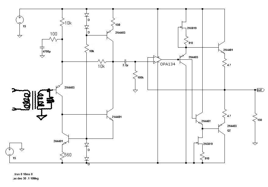
The transformer is a 1:2. Diodes are 1N4148.
The R in upper left, shown as 100ohm, sets the gain. The noise level decreases as the value is increased/gain is reduced. Removing it sets the gain at 6dB and the output noise is very low at that gain.

Here's the noise spectra, with grounded input Q base, as my sound card sees it:
noisyspec.jpg


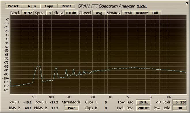
Any insight on this would be mightily appreciated.
 
Is that noise plot with >40dB of closed loop gain, or with the 100 ohm lifted?  If it is with the full gain, that noise floor translates to -125 to -130 referenced to the input which is not crazy for a 4403. (With the 1:2 transformer that input noise drops in half again).

I would have done several things about the discrete amp differently but if it stable and not oscillating it's noise should be pretty much defined by the 4403. 

JR
 
The main component of the noise is the hum at 60Hz and harmonics, probably from a grounding problem someplace.

In terms of hiss, you seem to be doing things right; the input 2N4403 is biased at about 1.1mA, which will produce the minimum noise figure at your transformer's output impedance (600 ohms with a 150 ohm input). And the input resistor of the feedback network is 100 ohms, below the 150 ohm value that would add 1dB of noise.

Two possible sources of excess hiss noise:

1. Are you measuring the output noise with a dummy plug connected the input? The dummy plug should have a 150 ohm resistor connected between pins 2 & 3 of the XLR.

2. What are the DC resistances of the primary and secondary of the transformer? They may be adding significant resistance, which translates into noise.

Peace,
Paul

 
First of all: please resist to show any schematic diagrams of this complexity without parts designators. It's very cumbersome to communicate without.

Besides what's been said a possible noise path is the 10k resistor from the positive supply to the emitter of the 2N4403 input transistor which leads to rather poor PSRR. Some voltage regulators show noise behaviour which peaks right in the audio frequency range because of interaction of regulator output impedance and output capacitor; the noise which you observe shows similar behaviour.

To check if that's the problem increase this resistor to 20k. If noise drops by 6 dB we got the bug. Possible solutions include RC filtering at this node or replacement of the resistor with a CCS.

BTW, why in the world do you load the output of your preamp with 150 Ohm..?

That noise floor translates to -125 to -130 referenced to the input.

The main component of the noise is the hum at 60Hz and harmonics, probably from a grounding problem someplace.

Be carefull with FFT plots. Without knowing the detailed FFT parameters you cannot judge the absolute noise level nor hum vs. random noise ratio. With the standard scaling factors doubling the FFT resolution makes the noise floor drop by 3 dB while the amplitude of periodic signals remains constant. Also the choice of FFT window alters the observed noise floor, and the shown numbers are presumably in dBFS which helps zero for absolute voltage levels without additional information.

Samuel
 
There is a cap loading the secondary of the IT. What value? How has it been determined? What is the IT? What DCR for the windings?
An other way of determining if the PSRR is at cause is the decouple the input Q's emitter resistor to ground, i.e. replacing the 10k res with two 5k res, the junction going to a 'lytic cap about 10uF.
 
Indeed that 10k connected direct to the + PS rail has zero PSR. Consider connecting it to the other side of that 100 ohm gain R, so the big cap filters it's noise too.

This may not be the source of the OP's noise complaint, since he said it is quiet at low gain, when the PS noise contribution coming in the 10k would still be present.

JR
 
Thanks, all.
I'm powering this with a stock Jameco power supply that uses LM317/LM337 regulators. Also, I have each power rail bypassed to breadboard ground with a couple of 220uF capacitors.
Hmm, I'm using a 150to600 ohm output transformer as a temporary mic input transformer for testing so that might be introducing noise as well or attenuating the mic signal in some way.
I was concerned because it sounds hissy when talking into a SM57 mic connected to its input.
The noise spectrum plot was with the input Q base connected to ground and scaled in dBfs.
I also have a .0033uF cap across the transformer secondary just to filter out some RF interference I was experiencing. Removing it has no effect on the noise level. There's a 10k R across the secondary too.
I'm testing the circuit with a 150ohm load simply because I might want it to drive a 150:600 output trans. at some point.
 
It looks like Samuel and John were on the right track: I had thought having some electrolytic filtering on the breadboard would be enough to clean up the +&-15V rails. Not so. I placed 15ohm resistors between the power supply outputs and the breadboard power rails and the preamp quieted right down. When I produce a PCB for this I'll have to be sure to include this kind of filtering for the high-gain section.
Thanks for the insight.
 
Sorry to be slow, but is this the conclusion: the noise you were noticing was coming from instability in the power supply rails, (indicated by 60 Hz in the  spectrum plot), and you got rid of it by placing a small value resistor between the power supply rail and the preamp power rail, before the 15 uf cap to stabilize and filter out noise?
I don't understand why the problem would exist only at high gain? 
 
> why the problem would exist only at high gain?

Input noise is multiplied by gain.

Samuel said: "noise path is the 10k resistor from the positive supply to the emitter of the 2N4403 input transistor which leads to rather poor PSRR."
 
PRR said:
> why the problem would exist only at high gain?

Input noise is multiplied by gain.

Samuel said: "noise path is the 10k resistor from the positive supply to the emitter of the 2N4403 input transistor which leads to rather poor PSRR."

Not to quibble but the change in current flowing down that 10k resistor due to PS noise, will be sucked out of that node through the 10k feedback resistor. It should show up in the output as roughly unity gain inverted, and not change significantly with preamp gain.

The input referred noise that will change with gain should be dominated by noise of the 2n4403 itself or coming into the base, which is why I said earlier this (PS resistor CM issue) may not be the source of the OPs complaint. Of course little things like where the - lead of the gain cap is grounded will look like a high gain input if not clean wrt to transformer ground.

JR
 
I knew going in that the circuit would have poor PSRR. I just wasn't knowledgeable enough to suspect that regulator-generated noise would be coming out of my test power supply. After I added an RC filter of 15ohms & 470uF to each power rail, the circuit got quiet at its gain of roughly 40dB. Test with mic input sounds good. The 60Hz with harmonics you see in the "before" noise plot is, I'm pretty sure, just caused by a ground loop between my experimenter breadboard and the input of my audio computer's sound card.

I believe the input circuit is a form of current-feedback opamp. It's inspired by the Neumann V476 preamp input circuit, simplified. I AC-couple it to a buffered IC voltage follower to: remove any DC component without having to capacitive-couple the output, and as an attempt to minimize odd-order distortion.

The circuit also works with just the input amplifier stage and the buffer stage without the IC (with a cap on the output) and after some more experimentation I may end up going that route.
 
Not really what most people would call an opamp, since there's no differential input. What you have there is a classic "feedback pair" -- two voltage amplifier stages, single-ended and non-differential, cascaded, with feedback around them. A lot of good amplifiers have been built that way.

Peace,
Paul
 
I had thought having some electrolytic filtering on the breadboard would be enough to clean up the ±15 V rails.

The output impedance of the regulator is low (at lower audio frequencies at least). Hence the capacitors cannot form an effective low-pass filter. In fact they mostly cause noisy currents flowing into ground where they can cause more troubles.

There's no differential input.

The emitter of the 2N4403 forms the inverting (current) input.

Not to quibble but the change in current flowing down that 10k resistor due to PS noise, will be sucked out of that node through the 10k feedback resistor. It should show up in the output as roughly unity gain inverted, and not change significantly with preamp gain.

Agree. I'd need to look into more detail but I presume that loop gain of this amplifier reduces in proportion with signal gain above about 40 dB because of finite input impedance of the inverting input. This reduces PSRR above 40 dB; such behaviour can be observed for many ICs too, see e.g. INA103 datasheet, page 7, top left figure. PSRR (as shown RTI) does not increase above 40 dB.

Samuel
 
Back
Top