Inexpensive Single Sided G7 build

GroupDIY Audio Forum

Help Support GroupDIY Audio Forum:

This site may earn a commission from merchant affiliate links, including eBay, Amazon, and others.

Blue Jinn

Well-known member
Joined
May 28, 2009
Messages
406
Location
USA Northwest
Single sided G7 build. Schematic found here: (xaudia blog)


G7hack1.jpg


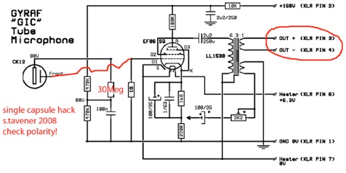
Mic started out as a MXL9000 which I got a sweet deal on. Didn't have the PSU, and then I "had" to take the capsule out for a (single sided) "BigUgly" so repurposed this one for a G7. I negligently damaged the AA Bv8 transformer I was going to use so I used a 3U Audio 6.5:1 transformer.

I also couldn't fit the 2u2 capacitors I have, so had to go with a 1uF I had on hand. Soviet 6Ж32П Tube. Capsule is Chinese originally from WGT, edge terminated C12sh clone. PSU is  a Chinese zener regulated board from Ebay with a 150VAC toroid. I used the datasheet for a 78xx not the one on the board. I can only get 150VDC unloaded, but it seems to work OK.

I changed the voltage divider to 470k and 270k to get about 50v at the capsule. For some reason I couldn't find an axial 100uF/35 volt electrolytic for a decent price at Mouser, which is why that radial is shoehorned in there.

Total cost of the build will be well under ~US$250 give or take including everything else: the case for the PSU, cable,  XLR plugs and sockets, etc. Mic body was only $20 though. On optest mic is nice and quiet, a little bright, sensitive even though I'm not the tidiest builder... Going to try it out soon! I don't know how "good" it is, but it was a fun build.

attachment.php

attachment.php

attachment.php


What is the function of the 30 M.ohm resistor, connected to the backplate?

And about the 100 uF capacitor: the voltage over this capacitor won't even be near 35 V.
Measure the voltage when the microphone is in operation, and you will see that there is only a couple of volts here!
 
Thank you for the comments. I went exactly by the schematic except for the output coupling capacitor. I had to read this thread https://groupdiy.com/index.php?topic=28519.20 to try and  understand the 30MOhm capsule bias resistor. I don't know why with a single sided capsule it can be lower than 1GOhm if it affects low frequency response and sensitivity.

 
RuudNL said:
What is the function of the 30 M.ohm resistor, connected to the backplate?

The capsule is polarized through that resistor. But i would use way higher value there. Maybe lower value is used as a tribute to elam or c12? It maybe works with original ck12 but i'd go with standard 1G.

I think that capsule can take 80v no problem. You get less loise, and tube is driven bit hotter.
 
IMHO the 30 M.ohm resistor is useless, it could be 0 ohms. And this point could be grounded for AC. (Through the 100 nF)
The only goal is to have a polarisation voltage on one side of the capsule.
The capacity variations of the capsule generate a voltage over the 1 G.ohm resitor. That's it.

Since the capsule and the 30 M.ohm resistor are in series, you can exchange their positions.
So what you in fact get, is a series resistor between the capsule and the grid of the tube.
Besides introducing a minimal attenuation (a fraction of a dB), the 30 M.ohm doesn't add anything.
 
I wonder why you didn't used original PCB from MXL?  THis circuit could easily fit original board, even with the parts you already used. Nothing wrong with perfboard of course :)
I would remove 220R on cathode section and ground 1.6k directly. Potentially use potentiometer for 1.6k and adjust bias.
 
Blue Jinn said:
Thank you for the comments. I went exactly by the schematic except for the output coupling capacitor. I had to read this thread https://groupdiy.com/index.php?topic=28519.20 to try and  understand the 30MOhm capsule bias resistor. I don't know why with a single sided capsule it can be lower than 1GOhm if it affects low frequency response and sensitivity.
In a U47, the 33Meg resistor forms a LP filter with the 10nF cap so the voltage change when switching patterns is ramped in order to minimize the thump. It could be completely ignored in a single pattern configuration. Or the 10nF reinstated.

Can you do an experiment for me and the rest of the guys?
Can you measure the cathode voltage, first in the actual configuration, and second after grounding the grid?
I would think using a 1G resistor as grid-leak would result in significant negative contact-potential bias, which may significantly reduce idle current and gain.
Vintage tube mics never used such high values; it's been ventured it was due to the lack of 1G resistors at the time, which is simply ludicrous. Contact-potential bias due to grid current is not a published spec, so there is significant variability; in addition it varies over time. I think that's the reason it was not favoured by our elders.
 
abbey road d enfer said:
Actually it adds noise!

Could you explain more?

abbey road d enfer said:
Vintage tube mics never used such high values; it's been ventured it was due to the lack of 1G resistors at the time, which is simply ludicrous. Contact-potential bias due to grid current is not a published spec, so there is significant variability; in addition it varies over time. I think that's the reason it was not favoured by our elders.

Never say never ;) Hiller used 7Gohm for MSC1/MSC2 tubes in their very first SDC mics like M59 for example. But agree, it was uncommon. Sony used 100M in cathode followers (before C800G era), Schoeps max 180M, AKG max. 250M, Neumann max. 400M.

 
ln76d said:
Could you explain more?
This 33Meg is in seroies with the capsule; its Johnson noise adds to the capsule's noise. The latter is pink above the cut-off frequency, hence not very audible. The resistor noise is white meaning it extends over the whole audible range.
 
@abbey road d enfer


abbey road d enfer said:
Can you do an experiment for me and the rest of the guys?
Can you measure the cathode voltage, first in the actual configuration, and second after grounding the grid?

Hi, sorry to take so long to reply, I built a different power supply (actually just modified a MXL V76t supply I picked up)  for 150vdc B+ now.


Cathode voltage is 1.5VDC with or without the 1G resistor.
 
ln76d said:
I wonder why you didn't used original PCB from MXL?  THis circuit could easily fit original board, even with the parts you already used. Nothing wrong with perfboard of course :)
I would remove 220R on cathode section and ground 1.6k directly. Potentially use potentiometer for 1.6k and adjust bias.

I had thought of doing that originally, and had a reverse engineered schematic of the MXL 9000 which I was working from. It seemed a lot more work to desolder components.
 
Blue Jinn said:
Yes, But then I also removed. Same. It's just slightly under 1.5v
I think he wanted you to measure the cathode under two conditions:

1) Normal, with the 1G in
2) Short the grid to ground with a wire

The 1G is in circuit in both cases.  Even tiny, minuscule grid currents can be transformed into significant grid voltages across 1G.  Measuring the cathode will tell you how 'significant' it actually is (unless I completely misunderstood what abbey was asking).
 
Matador said:
I think he wanted you to measure the cathode under two conditions:

1) Normal, with the 1G in
2) Short the grid to ground with a wire

The 1G is in circuit in both cases.  Even tiny, minuscule grid currents can be transformed into significant grid voltages across 1G.  Measuring the cathode will tell you how 'significant' it actually is (unless I completely misunderstood what abbey was asking).

I did all three.
 
Blue Jinn said:
Yes, But then I also removed. Same. It's just slightly under 1.5v
1G removed! The tube should not work without a grid leak. It probably means that there is another galvanic path between the grid and ground; it could be impurities on the PCB/ perfboard. can you check with the circuit not powered the resistance between grid and ground, with the 1G in place not shorted?
The cathode voltage should be maximum with 1G grounded, a tad smaller with the1G not shorted, and whatever without the 1G altogether.
 
Back
Top