Klark Teknik EQP-KT - Has anyone modded theirs?

GroupDIY Audio Forum

Help Support GroupDIY Audio Forum:

This site may earn a commission from merchant affiliate links, including eBay, Amazon, and others.

echoplex

Well-known member
Joined
Jun 29, 2011
Messages
195
Location
Germany
hi altogether,

klark teknik offers their eqp-kt for unbeatable 200€.
I can't even think of building a Pultec EQ for that price. The case and frontplate alone would be 200€+ !

So I was thinking of buying one or two and then mod the hell out of it.
Changing the tubes is obvious and probably crucial.
But has anyone tried to change capacitors and/or even resistors?
Maybe even trannies?
What's your experience? I bet there's people around here who's done it.

cheers
 
Like Jakob has said in other thread for the Behringer 1176 or LA2A clones,
it's really hard to go wrong when cloning this units.

You could always change the tubes, but maybe even the stock tubes are perfectly fine.

As for other components, it depends on the amount of SMD components the units had, from the picture I can't clearly see if there's smd or not. The stock resistors will probably be fine, stock film capacitors most probably also.
Electrolytic capacitors I'm sure they're not has good as any Panasonic 105degress series, and those could be changed for longer term reliability or for assurance.

Behringer Chinese made Audio transformers with Midas stickers, maybe they're fine, how could we know without some tests and some CJ's teardown?

I can see there's a Switch mode power supply,  as for the PSU it will depend on how well it's designed.
Well designed SMPS can be totally fine for audio.
The problem is when they fail and it's a pain to repair, or just not a worthy repair. And SMPS in this type of market are built to Fail most of the times.
So in a case of failure I would build a DIY linear PSU and ditch the SMPS, but I would use it stock as long as it works well.

Overall the unit seems quite well built, I'm sure it sounds good.

I would have to see some pics of the Front PCB (Audio)

I could only find these ones:

678765d1500405992-klark-teknik-pultec-clone-eqp-kt-kt-eqp-gut-shot.png


EQP-KT_Circuit-Board.jpg


large


5KRZU09.jpg
 
Documented somewhere that it and the WARM both use a non-original inductor approach, and the high boost bandwidth is much more narrow than a proper Pultec. 
 
EmRR said:
Documented somewhere that it and the WARM both use a non-original inductor approach, and the high boost bandwidth is much more narrow than a proper Pultec.

Thanks Doug, so that makes a good mod for the unit, modding  it for inductor based EQ
 
Is there any more info about the non original inductor approach ? Do they not use inductors all together or just inferior inductors ... Could the unit be made to be more like the original ... Thanks for info
 
I own 2 units... It s a funny Toy for the price and makes a moderate job...
In bypass It brings material up in your face, engaged It produce a sort of contour... The center frequency band Is turned a bit down... So for example on vocals you miss a bit of power
Once i was resetting the pots in bypass mode and noticed that low freq still affect the sound a bit!
16k range Is cool... A good shaping response
I chained the eq to kt2a for mastering and for that price you can get Better results than plugins... you can load the console out in manner that Daws can t do...So i left these units Always on the insert point of main out of my desk... Sometimes i engage them also for mixing or to shape stems
Funny Toys if you prefer real Gears
Best
 
1682324574468.png
Heres a photo of the main PCB from the EQP , as you can see its mostly through hole ,
The inductor can be seen just right of centre on the pcb , looks a little mean compared whats used in the real thing .
Some suggest a change of tubes brings improvements to the sound ,
Adding a proper power transformer externally on the back panel looks very possible , but that might require re-orientating the signal transformers for minium hum .
Some describe the sound as getting spitty in the high end at more extreme settings of the controls , maybe the puny inductor starts to saturate .
Now the new price is even lower than before the second hand value has also dropped ,
Im keeping an eye out for one .
 
I picked up an EQP-KT for 120 euros , arrived late today

First impressions are good , box seems solid and well screwed together ,
Pots have a fine detent , 5 clicks per division on the dial . They also have long metal bushings which meet the front panel and are locked down with a nut in the usual fashion , that way no force is transfered to the pcb when the control are used and it feels very solid and precise ,

Looking under the lid ,
262v HT off the SMPS, around 150mV noise at the output transformer centre tap ,
14.6v coming off the LT rail , regulated down to 12.6volts .

Someone changed out the 12AU7 , to a TAD selected ,
its seems like a good low microphonic tube ,
The Uli Buguera 12AX7 has the typical metalic clash you hear in most China made 12AX7's ,
its garbage and its for the bin as soon as possible .

I gave the unit a quick line check on headphones , sure enough with 60db gain
the stock 12AX7 rattles like a bucket of bolts , interactions with any of the controls are clearly audible , the bypass and frequency switches give a loud snap , even the pot detents are audible in the signal chain .

The noise floor is also bristling with porcupine spikes coming off the SMPS, lots of them ,
I'll have a look at that in REW tomorrow .
 
The rear PCB on the EQP contains the SMPS at one end , the xlr/jack sockets and the input transformer at the other , its not an ideal situation
Theres a lot of SMPS hash gets in and messes up the noise floor , its picked up by both the input transformer and the high range inductor on the front PCB and it varies depending on the settings of the controls .
Thats not what we want at all .......
Placement of the cored components seems suboptimal and might do with more care to better avoid unwanted interactions .

This thing is going to need surgery :)
first of all to amputate the I/O and transformer from the SMPS and make it into two seperate pcb's
then perhaps an external screened housing for the SMPS , to try and contains its garbage .

For anyone else out there who thinks the SMPS , the way its implemented in the EQP-KT does any justice to the circuit ,just dial up the noise floor and have a listen ,

Theres miles more sonic performance to be got out of this unit yet , just with the stock audio transformers,
the general feeling in the many of the user reviews was at higher treble boosts , the sound took on a gritty, grainy quality , not the silk texture that is the Pultec famed for .
Theres a reason for it , all that RF mush is intermodulating with your audio on the peaks ,


I have a couple of NOS heavy duty screened oil filled chokes , 8Hy ,
painted in jet black ,
Military radar grade components ,
If it puts manners on SMPS noise , its got a new home , on the KT backpanel ,

In the longer term I've a feeling Im going to be wanting an externally housed linear PSU for my
P-Uli-Clone , I dont like the more or less instant ramping up of HT that the SMPS does , with wars and tubes becoming ever more rare and expensive , no way Im subjecting any of my prized valve collection to that .
 
Last edited:
I took the chance to tidy up the messy lead dress around the output transformer ,
twisting the conductors with their respective pair ,
So Orange/Yellow is signal output ,
Green/Blue is the teritary feedback winding ,
Red/Brown are the to the anodes of the 12AU7 ,
and white is the centretap to HT line via a 50 ohm resistor and capacitance .


The windings measure as follows with the DMM ,
White-red 106 ohms 1/2 primary 1
White-brown 114 ohms 1/2 primary 2
Green-Blue 110 ohms FB winding
Orange-yellow 96 ohms output .

On the Atlas LCR
the following values

Primary inductance (series)
4.468 H
220 ohms at 1khz
Secondary inductance , 468mH
109 ohms at 1khz

I might have to look out for a suitable cake tin to try housing the SMPS externally to the back panel of the EQP instead
If that doesnt work , it needs re-housing in its own box ,
 
Im currently dreaming up a low cost external linear PSU for the EQP and possibly other lower powered tube circuits .

Seems likely an Ireland/UK universal shaver transformer will serve the HT , there cheap ,safe and available off the shelf from any electrical retailer , you have the option of either 110 or 230 volts output from a 230v line , alternatively it could be wired for 110v input and 230v out .

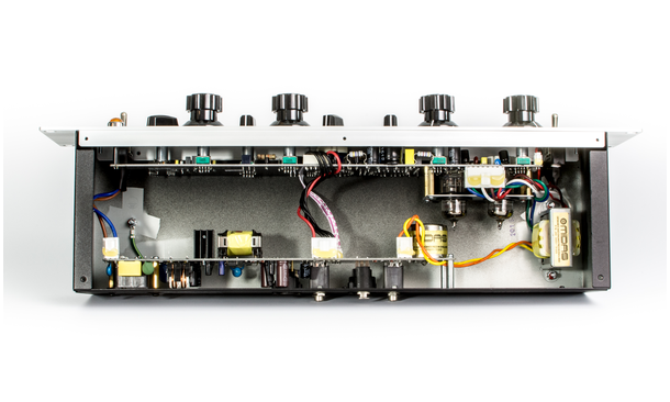
It looks a little difficult to sepperate the SMPS from the I/O on the EQP , its not a straight line on the PCB ,but it could be cut
I took a look at the components at the audio input , it seems like theres a 10k:1k resistive divide before the transformer ,SMD , likewise the output has the usual resistive termination , I guess theres no issue rewiring the audio onto discrete TRS and XLR sockets , with traditional resistors instead of SMD .

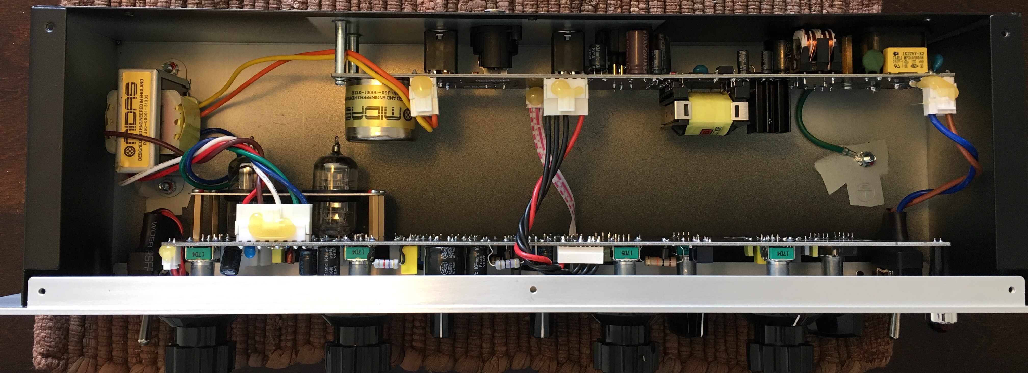
The heater rail as I said is DC 12.6 regulated down from around 15V via standard 317 , I didnt check if its elevated from ground, but the original Pultec does this with AC heater feed ,

I'd be tempted to try AC heaters for the simplicity it brings , but Id prefer not to have to hack the PCB all to hell , so maybe I'll just stick with the 15Vdc rail .

The HT rail hits the output stage unregulated , 1uF at the SMPS out , through a 50 ohm resistor , with what looks like around 220 or 330 uF to transformer center tap ,then its regulated down via a high voltage fet and acompanying transistor to the anodes of the 12AX7 .

All in all the design looks more perfect than the real thing , even the Warm audio clone has miles of cables here there and everywhere ,

What really lets this unit down is the SMPS , litterally spewing RF up the walls and into the inductive components inside the chassis ,
Im pretty confident with a decent external PSU the EQP could come a lot closer to the performance of the original Pultec ,

Look at the specs for yourself , the Pultec has around -110db noise , with the help of heavily sheilded high quality wound components
the P-Uli-Tek only manages -90db noise , thats mainly due to the RF shitsplatterer PSU residing inside the box :)

I found some great stuff here relating to the original Pultec ,thanks to the usual suspects in the know,

Oh yeah I found a section in the Pultec EQP manual that I got a laugh off ,
in bold lettering 'under no circumstances should boost and cut be applied simultaneously on the LF range' :D
 
An external PSU definitely has advantages, but I think you can also successfully solve this internally if you want to go the old school route.
1000027550.jpg

This transformer (or similar) is relatively small with a diameter of 62mm and would have sufficient power reserves.

That with a voltage doubler PSU for the heater and a B+ solution of your choice would fit if you throw out the SMPS.

At low loads, these toroidal transformers scatter little. If necessary, you can also build a shield around it.

I am confident that this would work...
 
Last edited:
Holger conclusively proved the worth of an off board PSU ,
doughnut or traditional iron core ,
I wont do toroids for high voltage ,
reason ? way less insulation than a modern dual bobbin EI mains step down
 
Holger conclusively proved the worth of an off board PSU ,
doughnut or traditional iron core ,
I mentioned that external PSUs definitely have advantages, but an EQ would be more than quiet enough with an internal solution IMHO. It was just a suggestion.
I wont do toroids for high voltage ,
reason ? way less insulation than a modern dual bobbin EI mains step down
I have not had a single problem with toroidal transformers in this respect in the last 38 years.

Good luck.
 
Call me cheap if you want , but Im really trying to keep build cost down to the absolute minimum while using easy to source of off the shelf components , The unit itself only cost me 120 euros used .

I dont mind sepperate transformers for HT and LT , in fact I prefer it like that ,
I can buy the shaver transformer for 15 euros ,
That can sit on the standard metal clad dual gang back box , they cost around 5 euros .
Theres no special tooling, cutting or drilling required , just add a cable gland at either end and your ready to mount up your components , The sockets will be removed and that allows space for the other components , I might do the LT in its own box with a blank front panel .

Shaver socket.jpgMK 2 gang metal clad surface box.jpg

Another quick and easy mod I did to my EQP is changing out the bypass toggle switch ,
I used a three way Switchcraft toggle from a Les Paul ,it allows me also incorporate a mute position or hard bypass via an extra set of relay contacts in the future .
The front panel hole has a notch and needed minor filing to make way for the Switchcraft bushing ,
 
The EQP drops the interstage transformer ,the feedback arrangement is also different ,
The tertiary FB winding isnt centre tapped , one side is connected to ground, the other side goes to the grid of the lower ECC83 section ,with resistive attenuation to set the FB level .
Unbalanced output from the filter goes to the upper ECC83 grid .

The EQP internal SMPS puts out a lousey 260v dc , the switching racket gets in everywhere ,
I'll use the 230v winding on the shaver transformer to make 300-330 volts DC ,
then follow with the traditional passive smoothing arrangement ,
The ECC83 anode supply is regulated with a mosfet and transistor ,
Heater supply regulates down from 14.6V to negative ground 12.6v , so the heaters arent elevated from the 0V reference , like in the original design.

The 10k:1k ohms pad at the front end presents a load of 20kohms to the source ,
but Ive read somewhere a Pultec needs 600 ohms to drive the passive circuit properly , resistance in the input transformer secondary causes the filter not to work as expected .
The input transformer is small , about the size of a mic input transformer , its probably 1:1 ratio ,
Would there be any advantage to putting a step down line input transformer ?
or another 1:1 transformer capable of handling higher input levels.


unnamed(1).gif
 
The EQP internal SMPS puts out a lousey 260v dc , the switching racket gets in everywhere .....

The tertiary FB winding isnt centre tapped , one side is connected to ground, the other side goes to the grid of the lower ECC83 section ,with resistive attenuation to set the FB level .
Unbalanced output from the filter goes to the upper ECC83 grid .
Hi there,
Am I understanding this right? So that means the EQP only uses one HT rail. Not a +250V (R17-C9)
and +290V (R16-C10) as in the Original's Schematic you posted? That "lousy"+260Vdc for V1 & V2?

Concerning input and interstage transfos, I understand the cost cutting process (get rid of this one) but surely Uli's minions could have put more thought into providing the right load/how the original circuit works. Or they simply didn't care/lets sell thousands of cheaper units ?!?

PS: I like "The Uli Buguera 12AX7" and "P-Uli-Tek"
I think you should "trademark" them and re-sell it to him, to serve him the same dish, but cold!
;)

M
 
Last edited:
The original derives two rails from one common supply , via two different filter paths ,
the KT has a sub regulated supply for the 12ax7 off the 260V , but the 12au7 is fed more or less raw HT from the smps , 1uF -50 ohms - 47uF - centre tap
EM Bleed from the SMPS transformer via the input transformer and high range inductor is a far more obnoxious source of noise than what gets in via the centre tap ,

So end of the day the EQP board only requires a single HT line and around 15v dc for the heaters to work , but a remote ,passively filtered PSU could give much better performance , larger values of capacitance with the same 470-1k-2.2k dropper resistors would cause a ramp up time of many minutes and give very low noise

Seeing as tube gear takes at least 30 minutes to reach a stable temp after power up the long HT ramp time up is no issue , in fact its beneficial for tube and capacitor lifespan , in contrast the KT SMPS ramps up to over 290V less than a second after power up , then gradually drops to 260v as the 12AU7 starts to draw current ,

So end of the day I want the SMPS gone from the EQP , in favour of passive filtered transformer supply ,
I'm putting together a prototype using a shaver transformer and two dual gang electrical knock out boxes back to back , with blanking plates as front panels .
I didnt settle on an LT transformer yet , the metal clad boxes are just over 40mm high so a low profile transformer is required ,

12V 20W R-core looks like a good fit ,
https://www.ebay.ie/itm/123783743952
 
Last edited:

Latest posts

Back
Top