Low battery power level with leds.

GroupDIY Audio Forum

Help Support GroupDIY Audio Forum:

This site may earn a commission from merchant affiliate links, including eBay, Amazon, and others.

lagoausente

Well-known member
Joined
Oct 2, 2006
Messages
288
Location
Spain
  Hello, I´m mounting my Supergreen preamp with CMOy headhpones amp, and a DI box designed by Samuel Groner in this forum, all in one 1U rack case.
   I have been using all them in separate cases before, and supply all them with 9V batteries. Supergreen with 4x9V and the other two with 2x9V.
  I´m thinking about using some low consumption leds of 1ma as power led for each section, but I have thought about add a battery power led but don´t know how to do that.
  I have been thinking at using a zener in series with the led,  but have doubts if a zener can regulate at 1 or 2ma.  There is also some leds that change color when battery charge drops. I could use two diferent leds instead, but how implement a circuit that switch off on led and switch on the other when the battery drops from the desired level?  Any idea?
 
Use a bi-color LED (it has 3 legs) and use 2 voltage comparators wired in a way that above a certain voltage level, the green LED is lit. Below a certain voltage level, the red LED is lit. It's the same LED, just depends on which comparator is lighting it up.

** of course, the comparator chips will by themselves use up power too.

I have been using all them in separate cases before, and supply all them with 9V batteries. Supergreen with 4x9V and the other two with 2x9V.

That could get expensive real fast.

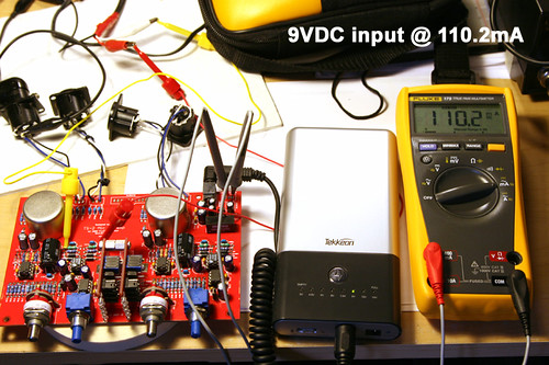
Here's my 2 channel preamp + 2 VU meters powered with 9VDC input.

2720233321_157cd14879.jpg
 
I made a simple level meter for an old kit I did back in the early '80s that might work for what you need.

A simple LTP is used to steer it's operating current (from collectors) between two LEDs. I used a two-color LED (3 legged common cathode). One tansistor is biased up to some reference voltage, and the other is a divided down from the battery voltage.

When exactly at the threshold, both LEDs will light, but it will have a failrly sharp transition. Tens of mV times input divider.

The majority of the current consumption goes into lighting the LEDs so is not wasted.

I used this for setting reference level for an old record playback NR (CX).  Above threshold was red, below green, and both LEDs lit was just right.

JR


That could get expensive real fast.

Have just ordered rechargeable Li-ion 9V batteries, with built-in protection ic. 400mah.  The preamp has around +-20 ma, so around 20 hours each cycle.  Probably will have more problems with my inspiration that with battery life.
   Cmoy and the guitar preamp consumption +-10ma each, and will have their own batteries, so 40 hours each cycle. http://www.batteryspace.com/index.asp?PageAction=VIEWPROD&ProdID=2644


A simple LTP is used to steer it's operating current (from collectors) between two LEDs. I used a two-color LED (3 legged common cathode). One tansistor is biased up to some reference voltage, and the other is a divided down from the battery voltage.

When exactly at the threshold, both LEDs will light, but it will have a failrly sharp transition. Tens of mV times input divider.

What LTP? 

The majority of the current consumption goes into lighting the LEDs so is not wasted.

I used this for setting reference level for an old record playback NR (CX).  Above threshold was red, below green, and both LEDs lit was just right.

I also have about using two leds instead of one two color, because the ones I have looked on Rs online two color have 10-20ma consumption, so near preamp itself.  Individual leds can find at 1ma and 2ma.
  Could you draw a quick schem with the LTP?
  Also have thought about using a zener as voltage reference, in series with a resistor and the led, calculating to get the 1.8V on the led, when battery is full, and when battery is low (zener Voltage), the led has minium light, so could see the charge as brightness on the led.  Could this work as well?   I would like to consider both options.
 
Just a simple differential pair...  two transistors with emitters tied together.. each collector to each LED. When one base is more than a few tens of milliVolts more than other you steer current to one LED or the other.

perhaps I'll draw something this weekend if you still don't follow, or try to find my old kit schematic.

JR


http://www.discovercircuits.com/H-Corner/9v-batmon.htm

Fancy chip, DigiKey has them for ~~$3 each. LTC1440CN8 is DIP-8, 800 in-stock at $2.75

http://www.solarbotics.com/products/8212/
http://www.solarbotics.com/assets/datasheets/bep-pm3-v2.pdf

A $3.75 chip.

 
Thanks for your replies. 

Just a simple differential pair...  two transistors with emitters tied together.. each collector to each LED. When one base is more than a few tens of milliVolts more than other you steer current to one LED or the other.

perhaps I'll draw something this weekend if you still don't follow, or try to find my old kit schematic.

  Sorry, I can´t follow it. I would like to see the schem.

Insert Quote
http://www.discovercircuits.com/H-Corner/9v-batmon.htm

Fancy chip, DigiKey has them for ~~$3 each. LTC1440CN8 is DIP-8, 800 in-stock at $2.75

http://www.solarbotics.com/products/8212/
http://www.solarbotics.com/assets/datasheets/bep-pm3-v2.pdf

Well, those chips are very low consumption, and easy to built.  :)
  Both options willl work for me.  The IC option, has the advantage of really no comsumption while battery is ok. But can we complicate things a bit, keeping low consumption?  What about a 3 stage level? Three leds, green, yellow, red. 2ma consumption each one. But working as tell JohnRoberts with the diferencial pair, so only one of the three is turned on depending on the voltage level. That would be better to see the discharging progress, so can calculate when to charge. Can do it with IC?
  Can someone explain me what´s hysteresis for?
 
How about a 10-LED battery level indicator?

Just use an LM3914 chip, and set to "dot" display mode instead of "bar".
 
owel said:
How about a 10-LED battery level indicator?

Just use an LM3914 chip, and set to "dot" display mode instead of "bar".

Well, that´s a good option when using only one battery, but I use 4 batteries in the supergreen, so put 40 leds would be no much practical.  Don´t exist a middle point IC?  Something for 3  or 4 leds? That would be more reasonable.  I have seen aswell a brightness controller chip, with and adjustment pin, so could have a brightness controlled by a voltage, another option with only on led.
 
OHHh... so you want to monitor EACH 9V battery? 

I thought you only want to monitor the total voltage going into the system.

Well, there's the quad comparator chip.
 
I made a circuit once that simply flashes the LED briefly for low battery.  Saves significant current especially if mated with a micropower comparator and voltage reference.

Now that LEDs are so much more luminously efficacious it's not quite as important.
 
owel said:
OHHh... so you want to monitor EACH 9V battery? 

I thought you only want to monitor the total voltage going into the system.

Well, there's the quad comparator chip.

What quad? Cannot find that chip.

Exactly I want to monitor 8x9v batteries. 
4x9V batteries in the preamp, 2x9v in the headphone amp, and another 2 in a DI box.
Thinking it well, the better would be one led for each battery.  Maybe with brightness controller, adjusting the current through the led in the range of the voltage drop, full voltage full brighness, low voltage very low brightness.
Or even with two leds, one like the one before, and the other switch on when voltage drops to minium the battery acepts..
Although the 4 led versión maybe could make a beautiful box. ummm.  I would like to have a look at that quad chip. But don´t find it, it´s from National aswell? 
 
Do you mean this one http://es.rs-online.com/web/search/searchBrowseAction.html?method=getProduct&R=5342696?

If it is, I have no idea how to implement the circuit.
 
> Just a simple differential pair...

Needs a reference voltage too.

Unless you wanna do something clever with Vbe.

Even so, if he's not shy about $56 of batteries, I'd think he could spring for $24-$48 of simple chips rather than mess with a lot of drifty transistors.

The quad-chips may not be wise. Which battery do you power it from? If that battery is weak or missing, the others are not monitored. That's why I was suggesting simple one-input monitors.

Any solution may have to account for some batteries positive and some negative of common. Another reason to KISS and use single monitors.

I also do not know if this LiOn chemistry can be sensed for "partial discharge" using simple voltage monitoring. I know one box started with NiCad and switched to Lead because a NiCad goes 1.2V, 1.2V, 1.2V, 1.2V, 1.2V, 0.8V, 0.1V.... you get almost no warning that it is about to quit. (Lead sags gradually, 12.7V-12.0 is easy to interpret, and it will not sag real fast even at 11V.)

When I must run batteries professionally, my policy is to use batts which will last the whole show, then change them at intermission just to be sure.
 
PRR said:
> Just a simple differential pair...

Needs a reference voltage too.

Unless you wanna do something clever with Vbe.

Even so, if he's not shy about $56 of batteries, I'd think he could spring for $24-$48 of simple chips rather than mess with a lot of drifty transistors.

The quad-chips may not be wise. Which battery do you power it from? If that battery is weak or missing, the others are not monitored. That's why I was suggesting simple one-input monitors.

Any solution may have to account for some batteries positive and some negative of common. Another reason to KISS and use single monitors.

I also do not know if this LiOn chemistry can be sensed for "partial discharge" using simple voltage monitoring. I know one box started with NiCad and switched to Lead because a NiCad goes 1.2V, 1.2V, 1.2V, 1.2V, 1.2V, 0.8V, 0.1V.... you get almost no warning that it is about to quit. (Lead sags gradually, 12.7V-12.0 is easy to interpret, and it will not sag real fast even at 11V.)

When I must run batteries professionally, my policy is to use batts which will last the whole show, then change them at intermission just to be sure.

  Thanks PRR,  some interest points to have in account.

  Can spend some $24-48$ on chips if I get happy with the final setup.
  Good point about the Quad supply. Discarded.
  The Li-ion batteries come with a buil-in IC circuit. The pdf tells that nominal voltage is 7.4V, and cutoff voltage from the IC is at 5.5.  I have just realized that maybe it´s a too low voltage.  That would mean a range from +/-14.8V, and +/-11V.    If the IC behaviour of this battery is similar to laptop ones, that would mean I would have that range, so could use the chips to detect the low battery. If the voltage keeps at 7.4 V, till the battery is discharged, than would be a bad new for the led, but a good new for the preamp voltage.  So, I´ll have to test mysefl when the batteries arrive, or ask the seller.
  I don´t use the batteries professionally, so I´m afraid I will not be on any show  :'(
  I´m building a setup with a laptop, in a case of 70x40cm, a magma chassis (pci-pcmcia adapter),Creamware Scope DSP card, preamp, ad, da etc, all battery powered.  It´s much for "cable free" setup, than for any other reason. I also have the M-audio wireless Midi Mid-air (not the keyboard, but the emitter-receiver).
  I´ll avoid some discussion with my girlfriend about order, psus, tangle of cables around and so on...and a plus of comfort for myself, and time saving. I have no studio now, so I have all that in a case that I take sometimes to play in the living room, or maybe somewhere out of home, when my girlfriend or my neighbourse get angry  ;D.
  Since the preamp itself, I use it only ocasionally, maybe I could use alkaline batteries, or maybe the NIMH 9V that I already have. That go from 7.2 V to 9V. Tha bad thing on this, are the high-self discharge.

  Regarding the low battery theme. What about this: If I take a zener of 5.5v, and put it in series with the a resistor and the led.,  , calculate the resistor to max consumption of 2ma,and a voltage decay of for 1.9 Volt.
  If the battery falls, since the zener keeps the voltage, will drop the voltage almost in the resistor, and so the current will drop, making the led less bright.  Wouldn´t work this aswell?
 
> current will drop, making the led less bright.  Wouldn´t work this aswell?

Your eye is not very good at judging brightness. Especially if ambient light changes. If you are near a window, 10mA in the afternoon looks dimmer than 0.5mA at midnight.

> If I take a zener of 5.5v, and put it in series with the a resistor and the led, calculate the resistor to max consumption of 2ma

Let's look at the specs.

Nominal Voltage  7.4V
Min. Dischargeable Voltage 5.5V
Max. Chargeable Voltage 8.4

Let's try your 5.5V Zener and a 1.9V LED, 7.4V nominal. Max battery 8.4V. 8.4V-7.4V= 1V in resistor. Max current 2mA. Use 1V/2mA= 500 ohm resistor.

Now when battery drops to 7.4V, current drops to zero. The LED is "off" (or very-very dim-- the "5.5V 1.9V" are round-knee curves) but the battery still has almost 2V of sag left in it. For typical Li-Ion, half the energy is still left.

I know Red LEDs best. Good ones are 1.5V at very low current and 1.6V at 10mA. Let's set the warning at 6.5V. At this point the LED is nearly off so 1.5V. Assume a 5V at 0.1mA Zener (this may be a nominal 5.6V Zener). At full charge we may have 8.4V in battery, 5.6V in Zener, 1.6V in LED. 1.2V difference, 2mA suggested current, 600 ohms.

The tricky part is getting Zener+LED voltage at LOW current to equal battery voltage at low charge. The low-current end of operation is not well specified on most Zeners. You could buy an assortment and test them.

You still have the problem that it is a dead-waste while the battery is full, it is hard to judge 2mA bright versus 1mA bright an hour later, and an LED fading out over a period of hours is not as attention-grabbing as an LED which suddenly comes on.

I do think the chips are a better idea. You can trim the resistor-ratio for desired voltage. (Hysteresis is not important here.) They are negligible power until the battery goes low, and then they can come on quite brightly.

Do you even NEED fancy batteries or monitors? Cmoy tends to be 20mA, the Green not much more, and a DI box is probably low current. That $8 battery is 400mAH.... it would run any one of these loads for 20 hours, or all three for 6 hours. How long can you play before your fingers/lips/arms hurt? The battery is rated for a very quick charge.... if you stop for dinner, the batts can be nearly full before you finish your after-diner cigar. And if you are not doing this all day every day, isn't a 50-pack of disposable 9V batts cheaper than Li-Ions, chargers, and monitors?

OTOH, if you truly need long run-time (camping in the woods), there is a 12V 2AH lead-acid battery used in burglar alarms. Two of those would power these chips for 40 hours, or a whole week of 8-hour days. And unlike Li-Ion, you can recharge the 12V lead batts by hiking back to the car, idling it, and clip-leading each batt to the car. Don't race the engine, the little batt can't stand the FULL output of a car charging system, but I top-off my lawnmower batt this way each spring. Lead will stand a lot more abuse than LiIon.
 
Lead will stand a lot more abuse than LiIon

Well, I have read the opposite. Lead have the advantage of price/mah ratio, so a big battery will not suffer because will not discharge a lot %.  Li-ion in the other hand is more expensive, and so the mah usually are less. But you can totally charge and discharge a Li-ion about 1000 cycles, and even that batteries suffer less with full discharges than with partial charging/discharging.
   Lead are cheap, but more weight, but they will suffer more degradation for higher discharges in %, and don´t like full discharging. , Have a look here:   http://www.batteryuniversity.com/
  There is a reason why I prefer rechargeable over 50 pcs disposable batteries.  With disposable, I have to open the preamp each time I need to replace, one or more batteries. With rechargeable, I can buil a conector in the rack to charge them. One estereo mini-jack, can work for two batteries, just attach that mini-jack to the Switch DPDT, to the pins that make contact when the preamp is off. So I assure that if switch is on, the mini-jack will make no contact to batteries, and switch off,  mini-jack go to batteries, but batteries don´t go to preamp.
Since I have ordered 8 batteries, I will have separate voltage for the preamp, for the Cmoy, and for the DI box. The only doubt here is if 7.4 nominal, 5.5voltage will be too low for the Supergreen?  With 6V, +/- 12V would be still ok? 
In the other hand, that 8 batteries will give me the 20 hours each section, what is more than good for just 1 hour charging.
  The chip solution is good really. The reason I thought about the zener-diode-brightness, was because I thought that having a led as indicator of "power on".  It have been happened to me, to forget switch off the Cmoy or the preamp, and get a discharge battery the next day. I think the chips are a good idea really, but maybe I could try the brighness aswell fot the "power on" led. The red leds, I have added on RS to my basket have a typical 1ma consumption, what I don´t think is much waste, don´t think there is much diference between 20ma, and 21ma really.
Regargind to the led, I have tried yesterday with one 6.4V, that seem to stabilize quite well the voltage even on uA, so I must check a zener with a good curve on low current. I have made aswell some calculation, what could be wrong, of course, but I want to make the try. It was some adventure, but at first I see they fit:
       R= AV/AI     AV= 8.4-5.5V= 2.9V. Put a more realistic range, for example, 8Vmax, 6Vmini, so AV=2V.
 
       AI,  let´s put max 1ma, min, 0.3ma for example, so AI=0.7 ma
 
                   R= AV/AI=  2V/0.7ma=  2.85k

   The voltage on the zener and the led vary very low, so calculate for average voltage:
    Taking the battery max at 8V and 1ma, as I take before, that would be, 8V-1.6V (led)-2.85V (resistor)= 3.55v zener.
  Since Vresistor= IxR= 1ma x 2.85k= 2.85V
Now calculate for minium voltage of the battery at 6Volt to see if fits.
The zener if were perfect, would still have 3.55V. And led 1.5V. That is, 5.05volt.  The voltage on the resistor will be 6V-5.05V= 0.95V, what would mean I=V/R = 0.95/2.85k= 0.33 ma. So if the zener would be perfect, and my calculations are ok, the range of amperage through the led ca be adjusted with the resistor.
  If we take the zener on 0.3ma would be 3v, instead of 3.55V, that would give:   3V+1.5v= 4.5volt.
  6V-4.5V= 1.5V on the resistor.     I= 1.5V/2.85k= 0.5 ma.  So the range would be in that case 0.5ma-1ma, so I suspect that adjusting the resistor to get more theorical variation, could compesate the final behaviour depending on the Zener specs.
  Let me know what you think about this.
   I would need to adjust the resistor to have a real amperage range. Could use this on the power one led, but aswell ad the low battery led with the chips.
 

Latest posts

Back
Top