Hi guys,
I was hoping someone much smarter than me may have a bright idea where I'm going wrong! I've completed a few projects of this site, but haven't posted too much (I've been reading rather than talking!). I've just got a little problem I can't find anything about searching on this site.
Over the past year I've bought about 5 Filtek EQ's, and successfully pig-tailed a few of them for use. They're great, a real find.
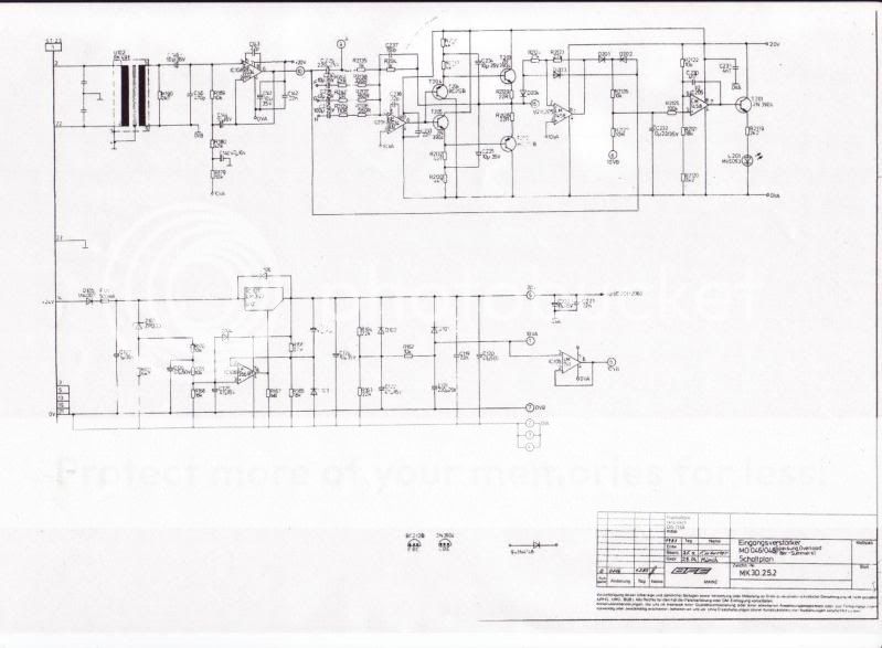
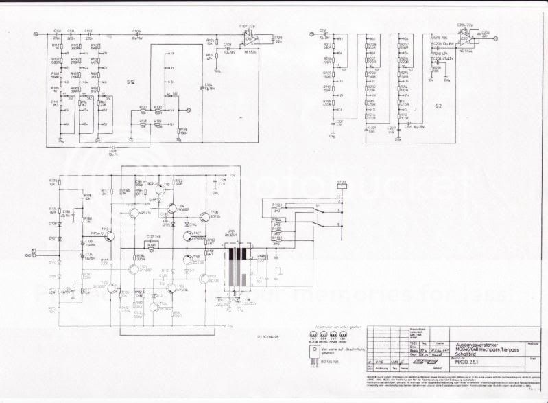
I'm just having a little trouble with the MK2 and 3 EQ's I have. The schems are here-


There's another schem file but it just shows the resistors needed for each frequency band etc, so it's got nothing to do with the pinouts.
From reading the schem and opening it up, I've figured out that-
Input cable- 2 and 22 (pos and neg), 21 and 3 ground/0v (I assume there are two grounds incase different consoles had different ground points, this would make the units a bit more versatile).
Out cable- 6 and 18 (pos and neg) 19 and 5 ground
Power input is on 14
Power ground is on 13
Chassis ground is pin 23
Internally pins 3, 5, 13, 19 and 21 are all linked (all 5 grounding points). They are NOT linked to the chassis ground though.
I'm intending to make a little carry case for the 5 units and power them off a JLM powerstation, but in the interim I'm just using wall wart 24v power supplies. I simply split the pos and neg wires on a power supply and send one to each unit. This has worked really well on the other Filtek units I've had (Mk5, which are essentially the same unit but smaller and with a different pinout and Tuchel connector that is only 13 pins rather than 23).
So, long story short, I've wired all this up and with the unit in bypass, signal is passed through perfectly- which suggests that the inputs and output wiring is good. As soon as I engage the unit, nothing but silence. I've also experimented with linking the grounds to the chassis ground via a single wire from 13-23, but no change. Unforunately, it doesn't have a power light so I can't tell you if they are powering up or not, but I'm thinking probably not.
Sorry to bug you guys, I was just wondering if you've got any ideas on where I might have gone wrong?
Thanks!
I was hoping someone much smarter than me may have a bright idea where I'm going wrong! I've completed a few projects of this site, but haven't posted too much (I've been reading rather than talking!). I've just got a little problem I can't find anything about searching on this site.
Over the past year I've bought about 5 Filtek EQ's, and successfully pig-tailed a few of them for use. They're great, a real find.
I'm just having a little trouble with the MK2 and 3 EQ's I have. The schems are here-


There's another schem file but it just shows the resistors needed for each frequency band etc, so it's got nothing to do with the pinouts.
From reading the schem and opening it up, I've figured out that-
Input cable- 2 and 22 (pos and neg), 21 and 3 ground/0v (I assume there are two grounds incase different consoles had different ground points, this would make the units a bit more versatile).
Out cable- 6 and 18 (pos and neg) 19 and 5 ground
Power input is on 14
Power ground is on 13
Chassis ground is pin 23
Internally pins 3, 5, 13, 19 and 21 are all linked (all 5 grounding points). They are NOT linked to the chassis ground though.
I'm intending to make a little carry case for the 5 units and power them off a JLM powerstation, but in the interim I'm just using wall wart 24v power supplies. I simply split the pos and neg wires on a power supply and send one to each unit. This has worked really well on the other Filtek units I've had (Mk5, which are essentially the same unit but smaller and with a different pinout and Tuchel connector that is only 13 pins rather than 23).
So, long story short, I've wired all this up and with the unit in bypass, signal is passed through perfectly- which suggests that the inputs and output wiring is good. As soon as I engage the unit, nothing but silence. I've also experimented with linking the grounds to the chassis ground via a single wire from 13-23, but no change. Unforunately, it doesn't have a power light so I can't tell you if they are powering up or not, but I'm thinking probably not.
Sorry to bug you guys, I was just wondering if you've got any ideas on where I might have gone wrong?
Thanks!


