Marshall 2203 (JCM800) oscillation with mods

GroupDIY Audio Forum

Help Support GroupDIY Audio Forum:

This site may earn a commission from merchant affiliate links, including eBay, Amazon, and others.

Matador

Well-known member
Joined
Feb 25, 2011
Messages
3,091
Location
Bay Area, California
Can anyone think of a reason why a stock Marshall 2203 (JCM800 from the mid 80's) would break into oscillation with a simple mod?
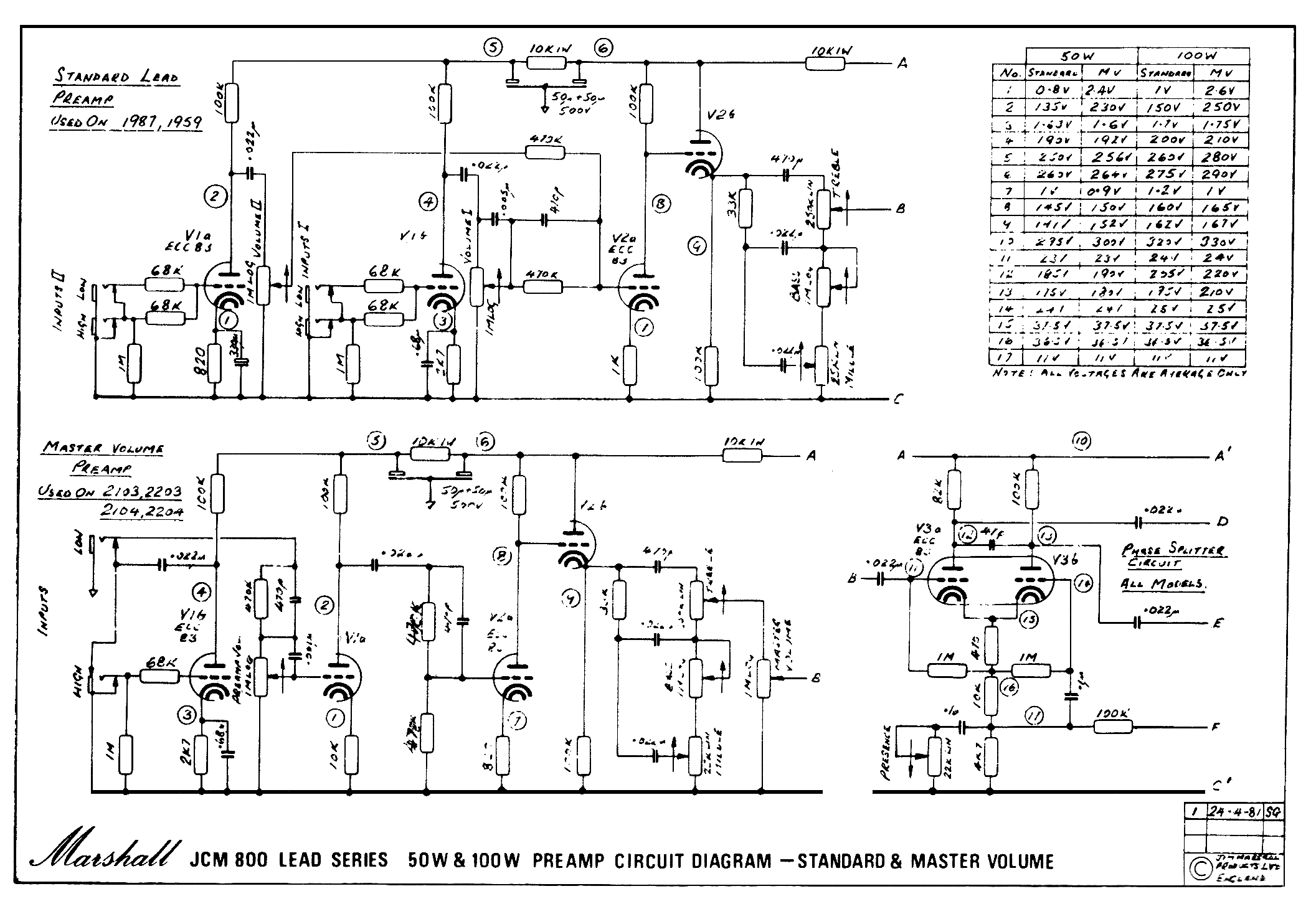
jcm800pr.gif

The mod is essentially adding a 0.1uF bypass cap across the 10K cold-clipper cathode resistor on V1A. Without the cap, the amp works normally. When the cap is added, even without a guitar plugged in (shorting jack), V1A screeches like a banshee at about 860Hz when the preamp volume pot is increased anything past 2 o'clock (leading into V1A).

Things I've tried:
a) Adding a 68K grid stopper directly to pin 2 on V1A - no effect
b) Shunting across V1B's plate resistor with a 220p cap to reduce high frequency gain in the front end - wailing is slightly quieter, but still happens.
c) Adding a small (47pF) plate to grid feedback cap in V1A - this stops the oscillation, however the tone of the amp drastically shifts to be less bright in overdrive tones.
d) Adding a blank plug into the low jack (breaking the connection between the first two gain stages) and the wailing stops
e) In creasing the 10K filter resistance in the power supply to lower the supply voltage going to the first two stages (from 10K to 27K): no difference
f) Half a dozen different tubes in the V1 position (even a 12AY7) all do the same thing, although the frequency of the screeching shifts slightly (between 750Hz and 900Hz) depending on the tube
g) Running a signal into the lock jack, and the amp works normally, just at less gain.

Any ideas? Obviously there is some parasitic feedback path that might just be on the edge with the stock circuit, that the added gain of the bypass on V1A is causing the amp to oscillate. The interaction must be between the first two stages. However none of these values are outside the range that I have seen in other high(ish) gain amps like the SLO, Rev, or Mesa's.
 
Have you tried a 250 to 470 pf cap across the 100k first or second plate resistor to see if it tames the oscillation? That’s used in many amps to help.
 
I did try a 220p across the first 100K. No change to squealing, however the top end did get slightly reduced. 470p darkens the amp significantly (and it still oscillates).

This is called an "aggressive clipper" mod, as it increases bottom going signal clipping above stock. It seems to work fine on other amps (even other 2203's), just not this one. 🤬
 
That 10 k cathode resistor without a bypass cap will provide a ton of negative feedback due to degeneration.

As soon as you put in the cap, you are getting rid of some of that nfb, there might be some phase shift going on also.
 
Interesting. CJ. Just thinking out loud. Should you lower the 100k feedback resistor on the power amp section to say 27k or change the ohm tap on output transformer to see if it stabilizes the over all gain. I know it’s in the preamp section but just wondering if it would stabilize.
 
Opening the feedback loop doesn't change the squealing, so the feedback is happening in the preamp section in isolation.

I get that gain is increased with the bypass cap, but the oscillation is perplexing. I'd like to understand the root cause so that I might be able to make alternate adjustments that might achieve the same result.
 
I don't recall other high gain amps having a cap there. You could isolate the problem further. Does the oscillation exist at the grid of V2a or does it develop further on?

If an identical 2203 behaves fine then it could be a layout issue. Consider what is different in the behaving amp. Lead dress and wire positioning is extremely important at high gain. I've had amps calm down simply by repositioning wires.
 
Last edited:
Did you try different caps? Ceramic caps are like antennas
And microphonic.

I agree with john12ax7--try moving some of the flying leads related to the preamp around and see if anything changes. Even a relatively benign (gain-wise) amp can have trouble with lead dress induced ringing. My '77 DR had trouble when I started clipping out the CBS era parasitic killer caps. Had to rearrange several longer wires and more or less duplicate the BF layout to get it under control. I still get it sometimes with the reverb set at Dick Dale levels.
 
Moving cables nearer to the chassis can help.
But maybe it needs better shielding.
Turn up the gain until it begins to oscillate.
Then try to shield parts of the (input) circuit with a small metal plate
connected to a ground wire. (postcard size or half of it).
when moving around the plate short circuits may happen.
Isolate the plate or be careful.
(as well: are the tube shields in place?)
 
disregarding your mods, this seems like a silly thing to mention but my own 1979 JMP 2204 started having some weird oscillation problems. Couldn't figure it out for the life of me, tried just about everything I could think of. Eventually replaced the V1 tube socket and issue went away. I think Marshall was still using the same sockets from the later JMPs on the 800s, at least until they switched over to the PCB mounted jacks.

Also, another rudimentary tip mentioned above that I'm sure you're aware of: when reversing mods on other 2204s and 2203s, which sometimes includes installing new input jacks, I'll run the hot lead off the input jack to the V1 grid with shielded wire grounded at the jack side just for additional stability. This has helped out with removing noise issues on other amps that share the Marshall style preamp circuit like a 1960s Laney Supergroup I restored.
 
I also had to replace some preamp tubes sockets after ripping my hair out for two weeks. Weird. Then there is that batch
of conductive fiberglass boards .

Adding that 0.1 bypass cap increases the gain of that hard clipper quite a bit. Especially at the higher freqs. Marshall's have never been the most stable amps in the world. So by increasing the gain you reach the cutoff point of stability.
 
I don't know why, but it is a common report that putting a 100n across the 10k cathode resistor causes oscillation. The common fix is to put a resistor in series with the 100nF. A value like 1.5k to 2.7k. Are you going for a Slash tone?
 
I don't know why, but it is a common report that putting a 100n across the 10k cathode resistor causes oscillation. The common fix is to put a resistor in series with the 100nF. A value like 1.5k to 2.7k. Are you going for a Slash tone?
This 100nF cap across the 10k increases gain by about 16dB above 2kHz.
No wonder the amp tends to oscillate.
Now, putting a 1.5k-2.7k resistor in series with the cap reduces the boost by 4-6dB, which may be enough to stabilize the amp,...or not.
 
It is often reported that the 100nF causes oscillation and the series resistor is reportedly the cure.
 

Attachments

  • Slash's jcm800 #34 SIR Frank Levi Mod.jpg
    Slash's jcm800 #34 SIR Frank Levi Mod.jpg
    79.2 KB · Views: 5
A few more tests:

1) Poking and prodding wires doesn't appear to change anything - there are two runs of shielded wire, one from input jack(s) to V1, and also one from the gain pot to V1A. Most of the rest of the affected circuitry is on the PCB.
2) Hard grounding V2A grid cures the oscillation (even with cap in place).
3) The plate for V2A is the first place i can clearly see the oscillation, however it's difficult because hanging the scope probe can change the behavior.
4) Hard grounding the "low" input cures the oscillation.
5) A shorting plug in the input *sometimes* cures the oscillation. Sometimes even hanging the scope probe on pin 7 causes it to stop, a few times it doesn't.
6) 100K grid stopper direct on V2A doesn't stop the oscillation.

I think this particular mod it to provide more of a high frequency boost, however I'm not sure the 14dB of gain is really critical itself: in other words, I think the EQ shift might be more important that the gain increase.

I wonder if lowering the 100K plate resistor to reduce some of the added gain might work, as it should be a "frequency neutral" gain reduction, right?

Is this a case of self-oscillation within V1? What is the feedback mechanism? A common positive feedback would be cathode to grid coupling, but I don't understand why that would be modulated so much by a cap on the cathode (in fact, bypassing the cathode should reduce any such coupling, as it puts the cathode more at AC ground at high frequencies, right?). Looking at the plate supply voltage in AC mode on my scope I don't see any wiggling on the voltage except a faint trace of 120Hz down below the mV level.
 

Latest posts

Back
Top