Mitsos API 312 / 990 Build Thread

GroupDIY Audio Forum

Help Support GroupDIY Audio Forum:

This site may earn a commission from merchant affiliate links, including eBay, Amazon, and others.
Hi mitros,

I've used the Sowter 4220 on my other API-312 preamps and they sound great with the line balancer.
I have two LA2A which I've put these 4257 txf on and they sound amazing.
Specs seem to think they will accept 18k:30k.
Also I'm going to try a 50k pot with a 47k resistor on wiper 1-3 to form a rev log pot 24k.

Regards

Spence.
 
hi,

progress has been made, i've put together one pcb with the Sowter 4257, also using 50k pot with 47k resistor on wiper 1 and 3 to give rev log.
Have had to put in quite a few links to get the signal through, but finally the signal arrives at THAT1646 nice level on pin 4.
pin 1 is much lower signal, so i've gotta assume the IC is duff, will try another IC from another line balancer which works so to remove this as an issue or not.

regards

Spence.
 
HI,

i made an error in a jumper, now only jumpered: C5, R4, R18, R11, DI switch, R21, R22, C8. works great now!!!
getting nice wave at end, just a matter of pluggin in and running some audio now.

regards

Spence.
 
I suppose ive never read/learned of that trick with the 47k on legs 1 and 3 to convert a normal log pot to rev log, can you explain how that works  or anyone care to point me somewhere i can read???
thanks
 
Hi,

Best to just try it out, but here's some info.

http://www.geofex.com/article_folders/potsecrets/potscret.htm

I can verify this works with 50k pots, 47k resistor on 1 and 3 wiper, then connect to pin 2 and what ever side you want for 24k Reg log.
Neat trick as I have loads of 10k and 50k pots.

Regards

Spence.
 
Spencerleehorton said:
Neat trick as I have loads of 10k and 50k pots.

Regards

Spence.

Lol. Yeah so do I, hense me wanting to know. Very cool.  Ive read of people taking apart rev logs and switching the insides with a regular log pot of the value needed when the reverse was hard to source but this is certainly resourceful. Something else for the toolbox in my brain anyways.  Neat.
Thanks man
Cheers
Dylan
 
HI,

nearly finished now, have tested with putting some audio through and all 4 channels sound amazing.
one problem, the pots are only working with all the signal at the end in a very small point, so this leads me to believe that the rev log resistor from wiper 1 to 3 isn't working properly.
Im going to try a few different ways to see if i can get a smoother gain level throughout the range.

regards

Spence.
 
Spencerleehorton said:
HI,

nearly finished now, have tested with putting some audio through and all 4 channels sound amazing.
one problem, the pots are only working with all the signal at the end in a very small point, so this leads me to believe that the rev log resistor from wiper 1 to 3 isn't working properly.
Im going to try a few different ways to see if i can get a smoother gain level throughout the range.

regards

Spence.

From the link you posted, I think it's supposed to go from 1 to 2, and then you leave pin 3 unconnected.  Look at the bottom of that page. 
 
There is another old thread for the PCBs in the LAB, I just saw it because someone posted to it.  Here is some info on servos and gain steps, thanks to member DMP:

dmp said:
The servo can be very slow - look at the components around it.  It is just correcting the DC offset of the DOA - not in the audio band.
The important specs I believe are a low DC offset. And if you are using 24v, you need a chip that can handle it. I've used OPA604 in 10 channels @24v and they work great.

dmp said:
I think this is what I used. Goes from 15dB to 70 dB in 5 dB steps.
Step 1 (70dB) has the 1.5 ohm on the switch, and the 4.7 on the pcb and they are in series. As you go up in the steps, the resistors keep adding.
The gain formula is G = 20*log(2*10000/R), where the 2 is the transformer gain.

4.7
1 1.5
2 4.7
3 7.5
4 20
5 30
6 47
7 91
8 150
9 270
10 470
11 910
12 1500

dmp said:
Here is the resistor values for 5dB to 60dB:
1 20
2 15
3 27
4 47
5 91
6 150
7 270
8 470
9 910
10 1500
11 2700
12 4700
 
Hi all,

Well I've done some testing now on trying to get a 22k Rev log pot from a 50 k Lin pot.
No success I'm afraid, best it works is the 50k Lin pot without any resistor?
Everything is still pretty much all at the end of the pot though?
Can anyone shed some light on how to actually to do this properly as I'm not getting it?

Regards

Spence.
 
Can anyone shed some light on how to actually to do this properly as I'm not getting it?
I'm going to be a smartass and say that the only way to do it properly is with a Reverse log pot!  ;D

I've actually never tried slugging, but from a quick look around it seems it's possible to imitate a log, but not reverse log pot.  I'd say call audiomaintenance and order some rev log pots.  Not the answer you want to hear maybe, sorry.
 
Yeah,
I do like what you've said as that is the conclusion I have come to, I have some switched pots which I could make up the values and make but I wanted  normal pots for this so I've ordered them.

A little update on my unit with microphones reveals that condenser mics  work with phantom power on channels 1,3,4 but not channel 2 so I need to look at that.
Haven't tried dynamic mics yet and not expecting ribbon mics to work with these sowter 4257 txt.
Will test and update for anyone else so they know.

Regards

Spence.

Regards

Spence.
 
Hi Ya,

just a final update, tested with dynamic mic, fine, ribbon mic fine.
Had a buzz on channel 2 when 48v engaged but turned out to be the TXF shorting out some points!
All sorted sounding massive apart from changing over pots to rev log when they arrive.

thanks again to Mitros and everyone, top darts.

regards

Spence.
 
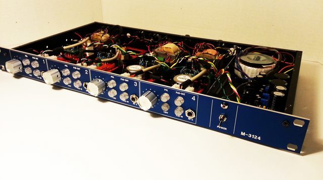
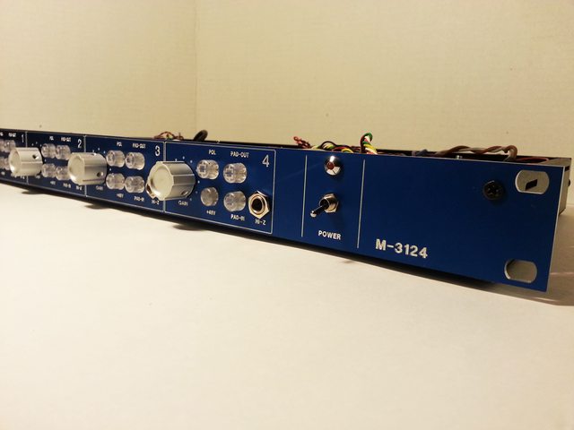
I am nearly done with my M-3124 (just need a couple of input and output xfmrs) but I needed to use it for a session so I figured I would take some pics before racking it.
It is great on everything (seriously) but especially metal guitar and drums drums drums.
lQ7l6ufl.jpg

tKdWTBEl.jpg

OAkdsIHl.jpg

 
i am finally almost done with my build

i am using an external power supply

i am not sure how to make a proper grounding

my idea is

- iec ground goes to psu chassis
- psu circuit ground to psu chassis
- 4 pin xlr to carry +/-24V +12V for the leds and +48V phantom
- ground tab of the xlr connects psu chassis ground to preamp chassis ground
- input and ouput xlr pin1 goes to preamp chassis ground connecting to ground tab on xlr connector

is this any good ?
 
beatnik said:
- iec ground goes to psu chassis
- psu circuit ground to psu chassis
- 4 pin xlr to carry +/-24V +12V for the leds and +48V phantom
- ground tab of the xlr connects psu chassis ground to preamp chassis ground
- input and ouput xlr pin1 goes to preamp chassis ground connecting to ground tab on xlr connector

is this any good ?

I would go with a 5pin XLR, take the PSU 0V to the preamps and use the cable shield as a shield, connect it to the metal cases but don't use that as your ground reference, use the PSU 0V for that.  The two get connected eventually, and  you may be able to get away with doing it the way you write, so if you already have the 4pin XLRs, you can try it and see if it works.

Each I/O XLR pin1 goes to case using short fat wire.
 
revisiting my 8x Mitsos 312 build, I would like to have two channels with lower preamp gain and am pondering on the best way to implement this.

I am using rotary switches for gain control and the lowest gain setting is currently around 32 dB. The input transformer is wired 1:7 (17dB gain) and the output transformer 1:2 (6dB gain). The lowest opamp gain is therefore around 9dB using a 2520.

any tips on getting output gain down another 6dB?

I am not sure how stable the 2520 is when I reduce gain down to near unity so I had been thinking wiring the 2503 output as 1:1 (utilizing the unused grey/violet secondary winding ). Any problems with that?

Or would it be preferred to wire the input transformer to 1:3.5 ratio?


EDIT: upon more searching around it seems this has been discussed in other threads. Wiring the input transformer 1:3.5 is reported to be not optimal in regards to noise performance with 2520 opamps. So I will try to tackle the output transformer...
 

Latest posts

Back
Top