modding a Moviola "squawk box" for guitar amp use

GroupDIY Audio Forum

Help Support GroupDIY Audio Forum:

This site may earn a commission from merchant affiliate links, including eBay, Amazon, and others.

donnysparks

Well-known member
Joined
Apr 14, 2005
Messages
129
Location
Birmingham, AL
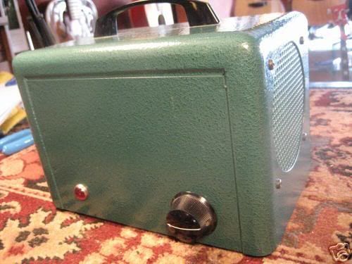
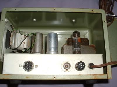
hi all. i'm hoping to convert this beast into a guitar amp. It's an old audio monitor device for film editing. it has a little 4" speaker and a headphone out. it apparently packs a mean 3-4 watts. i'd like to put a 1/4" jack on the input and maybe make some other adjustments to make it more suited for guitar. anyone want to help me decipher the schematic? it looks to me like maybe pin 2 of "PL-1" is where i might put the "tip", and pin 4 would maybe go to "sleeve". anyone? any obvious component changes i should make (input resistor values, cap values, etc)? any other ideas? i'd like some opinions before i dive in (again). Before i found the schematic i assumed that the threaded terminal was a hi z mic input so i put a 1/4" there. i got the magic smoke. oops, that was obviously something to do with power.

I have 2, so once i figure out the good one I'll take a look at the first one i "modded" :roll: .


17a9_12.jpg


DSCF0004.jpg


here is the schematic:

http://192.211.16.13/curricular/audio01/images/moviola.pdf

thanks in advance for any help!
 
Don't connect your pickup to pin2. Look more carefully at that schematic!

Do this instead:

Remove C1.

Connect tip to pin 3, sleeve to pin 4.

Other than that, the amp should be pretty useable as-is, although I do recommend adding a three-wire, grounded power cord.
 
[quote author="NewYorkDave"]Don't connect your pickup to pin2. Look more carefully at that schematic![/quote]

ooooohhh...225V. so my guitar (and my internal organs) shouldn't be seeing lethal high voltage?

whoopsie. I am glad that I asked!

Thanks so much for the reply. you very well may have saved my life.

:sam:
 
There was a thread or two about the Moviola on 18watt.com before they split the site into pieces. Might want to try SEwatt.com, as it's a single ended amp. Very cool looking box :grin:
 
well, i hooked it up according to NYD's advice, and it works! its a little noisy but makes up for it with lots of personality. That steel housing rattles like mad so i'm going to try to dampen the mechanical joints. It sounds loads better through an external cab--i tried it on my silvertone cab (Jensen c15p).

I checked out the 18watt site. i'll have to learn my way around there, as it was a bit confusing. i did find a couple helpful threads, though. Thanks!

I'll post back with progress notes. in the meantime if anyone has any other advice I'd love to hear it.

I love this place...

:sam:
 
I picked up several moviola chasses complete with tubes, well, everything for less then 50.00(US) at the local electronics. Said to be the amp for the speakers. Had all the makings of a guitar amp head just needed some tweeking. Less then 50.00 bones and I had a 15 watt head that I sold for a few hundred to an associate. loves the way it sounds...
 
i have one of these little guys and it has awesome grit. my internal speaker sounded really buzzy ontop of the mechanical rattling. mine is noisy too but im hoping a recap will help a little.

id read somewhere that it was recommended to upgrade the 470k input resistor to a 1meg for a better match. think its worth it? I might give it a try when i do my recap.
 
[quote author="Mbira"]What is that PL-1 on the input? "optical and magnetic" interesting![/quote]Optical and magnetic refers to the fact that it was originally used for film editing. Audio for film comes in either an optical or magnetic stripe on the film. For guitar amp use absolutely recap the power supply then rip out everything in front of the first 12AX7 stage. Replace the 470K with 1 Meg and then add anything from 10K to 100K resistor to pad the input like any good old Fender. These Moviolas make great guitar amps for recording or practicing but yeah they do rattle without some work.

Jesse
 
[quote author="outoftune"]id read somewhere that it was recommended to upgrade the 470k input resistor to a 1meg for a better match. think its worth it? I might give it a try when i do my recap.[/quote]

yeah, i think i'm going to try that.

For guitar amp use absolutely recap the power supply then rip out everything in front of the first 12AX7 stage. Replace the 470K with 1 Meg and then add anything from 10K to 100K resistor to pad the input like any good old Fender. These Moviolas make great guitar amps for recording or practicing but yeah they do rattle without some work.

thanks so much for the info, Jesse. re the 10k-100k, should that just go in series from the input between R2 and the 12ax7? i'm going to spend some more QT with this thing after xmas. i'll definitely report back with some notes.

again, i love this place!!!

:sam: :sam: :sam:
 
[quote author="NewYorkDave"]Remove C1.

Connect tip to pin 3, sleeve to pin 4.[/quote]

Whew, sounds like that was a close one...

You might also snip the leads to PL-1 pins 1 & 2, just to prevent someone else in the future taking a wrong guess at which pin goes where....

Leigh
 
To be more specific as to what to remove look at the modified schematic I cooked up. Changing the values of the coupling and bypass caps will give you more bass response.

tablebeastmoviola.jpg


You want to remove from the original schematic completely as follows: PL-1, PL-2, C-1, C-2, R-1, R-3, R-4, and R-13.

Replace C-4 and C-5 with .02uf 400+v caps, Orange Drop or similar. Replace the C-3 multi-cap with individual 25uf-50v caps at the 3 cathode bypass locations and the single 10uf-350+v filter cap.

Replace R-2 with a 1M resistor and R-7 with a 1M Log (audio taper) Pot.

Lastly replace the ungrounded two prong AC cord for a grounded 3 prong , install a 1/4" closed circuit jack for the input and a proper switch for power.
 
[quote author="tablebeast"]To be more specific as to what to remove look at the modified schematic I cooked up. [/quote]

wow! Jesse, thanks so much for taking the time to draw that out! i really, really appreciate it. your redrawn schematic is much easier to follow from a learning perspective, as well. i think i might also try adding a bright switch a la f*nder, as in here:

http://music-electronics-forum.com/showthread.php?t=1262

this is going to be a fun project.

[quote author="tablebeast"]Check this out[/quote]

yeah, that guy has been trying to sell that for awhile. look at my first post. i originally nabbed the photo of the moviola from one of his auctions.

i'm going to let these mods soak in a bit and try them out after xmas (going to the inlaws' so the soldering iron has to stay at home :? ).

check this one out:

http://cgi.ebay.com/MOVIOLA-VIRGO-TAPE-READER-MAG-SPEAKER_W0QQitemZ180160753142QQihZ008QQcategoryZ4790QQrdZ1QQssPageNameZWD1VQQcmdZViewItem?_trksid=p1638.m118

solid state, and doesn't have the nice hammered green finish that the moviola one does, but looks like it could make a neat housing for a new amp...

happy holidays everyone :sam: !
 
i might also try adding a bright switch a la f*nder

Well, there are a million mods you could do. The schematic I laid out just removed all the ******** film stuff and left you with the most basic amp layout for guitar. I would start with that and then add mods one at a time so that you can get a real feel for each tweak.

As a matter of fact, do the mods in this order for best results:

1. Remove all the unneeded film stuff first.

2. Then replace the Power Supply Filter Caps and cathode bypass caps.

3. Install the 68k resistor on the input. Install dedicated power switch.

4. TEST. Listen and decide if you need more bass response or gain. Use it with several external cabs and speakers in addition to the internal one for best results.

5. NOW, you can go and swap the grid load resistor in V1A to a 1M.

6. Test again.

7. Replace the volume pot with a 1M if desired.

8. Test again.

9. Replace the 0.006 coupling caps with 0.02 if desired.

10. From here you can experiment with a LOT of mods, just look around the net.

Good luck.
 
tablebeast, thanks so much for the mods. i am going to be getting to do some recap/mod action on mine, and this will make it much easier. i'll let you guys know how it goes!

also...does anyone have suggestions of a decent 4 inch speaker that will fit into this? im not expecting a miracle, id just like something that doesnt buzz like crazy when i play it at a reasonable practice volume.
 
[quote author="tablebeast"]
i might also try adding a bright switch a la f*nder

Well, there are a million mods you could do...[/quote]

Once again, Jesse, THANKS! That looks like a reasonable strategy that you've laid out. One thing about increasing the cap values for more bass response: in general, does that shift the freq response in that direction (ie trim off high end at the same time) or does it just extend the range? I feel like its a little dark sounding as is. but maybe replacing with new components will liven it up a bit. I can't wait to try this stuff out. almost wish i wasn't going on break just yet...

[quote author="outoftune"]does anyone have suggestions of a decent 4 inch speaker that will fit into this? im not expecting a miracle, id just like something that doesnt buzz like crazy when i play it at a reasonable practice volume.[/quote]

i would bet that anything that would fit in that small of a space would have the same problems as the original. maybe you could pad the speaker a bit? in mine, the most obnoxious buzzing is coming from the chassis, so i'm going to dampen the chassis before i look at the speaker. also, the resistor on the input that tablebeast mentioned may be all that is needed to get things under control. i doubt this amp was not originally meant to see a guitar level signal.
 

Latest posts

Back
Top