


- Joined
- Jul 15, 2009
- Messages
- 2,301
D-M269C Build thread
All of the info here : http://www.groupdiy.com/index.php?topic=49675.0
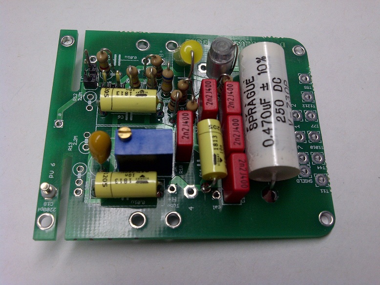
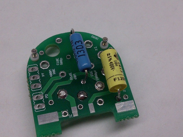
Attention R14 (plate) = 100K
Schematic Here : https://cdn.groupbuilder.com/groupdiy/u/39511/58d1402a04d0a.pdf
PSU Schematic : https://cdn.groupbuilder.com/groupdiy/u/39511/58d1402a04d18.pdf
Note : the Toroidal tranformer secondary is wired in parrallel to get 120V at the input of the psu
The 20Vac traffo for Europe will not fit as per the current BOM please replace it with this one or an equivalent ,
http://www.mouser.com/ProductDetail/Hammond-Manufacturing/186B20/?qs=sGAEpiMZZMvwUzoUXIIvyQPvPmwnNFGyR%2fQB%252b1BzrOY%3d
also The fuse will be 0.1A instead of 0.2 for America
IMPORTANT:
You Should always have the SHLF Jumper in position in the PSU PCB , this will ensure that your cable shield is tied at both end of the cable and connect to 0V
you Should Also have the 0V star grounded to your case and then from there to you IEC earth ground ,
For More Information on Grounding
https://www.dropbox.com/s/6y121dasm3iw4ba/Sound_System_Interconnection.pdf?dl=0
Cabling connection From PsU https://cdn.groupbuilder.com/groupdiy/u/39511/58d1402a04d39.jpg
D-M269C Overall Connection : https://cdn.groupbuilder.com/groupdiy/u/39511/58d1402a04d5c.jpeg
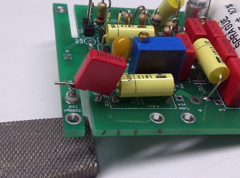
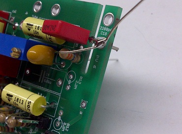
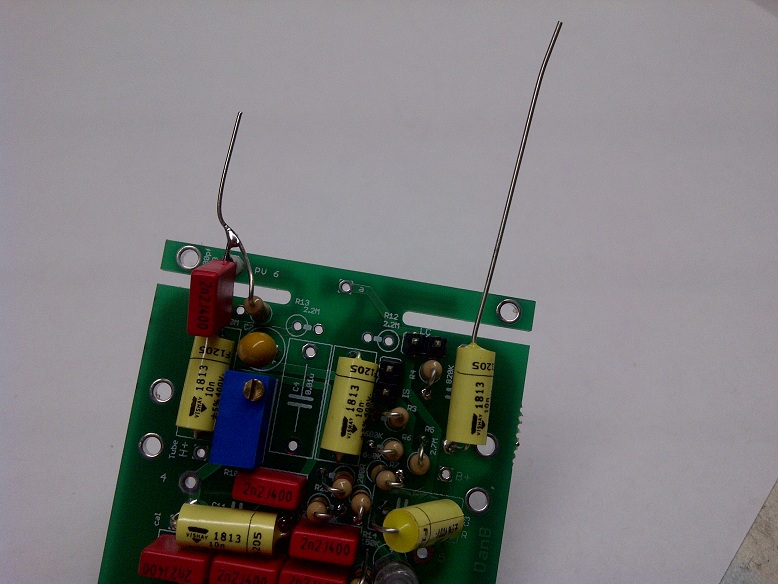
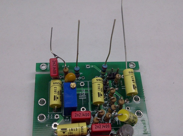
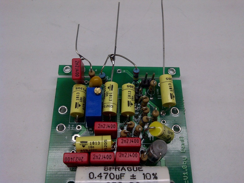
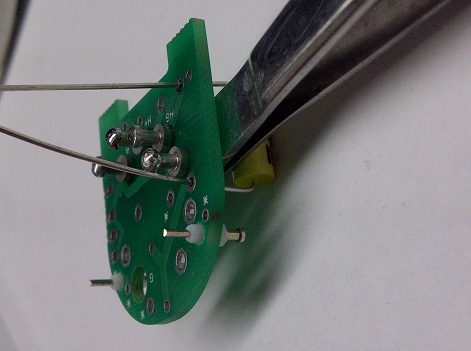
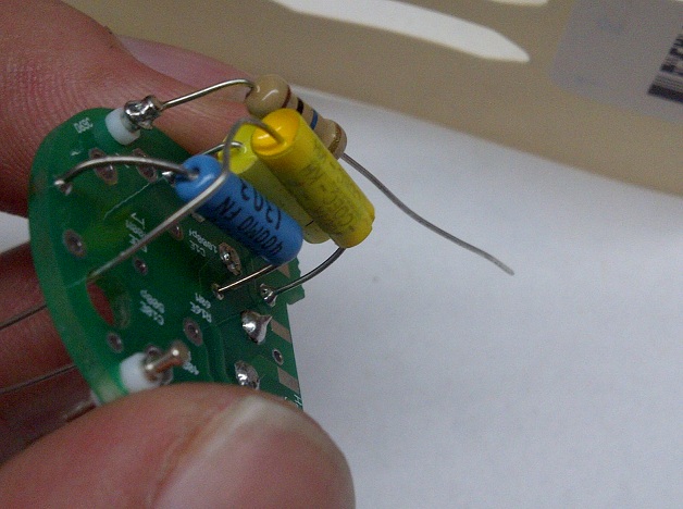
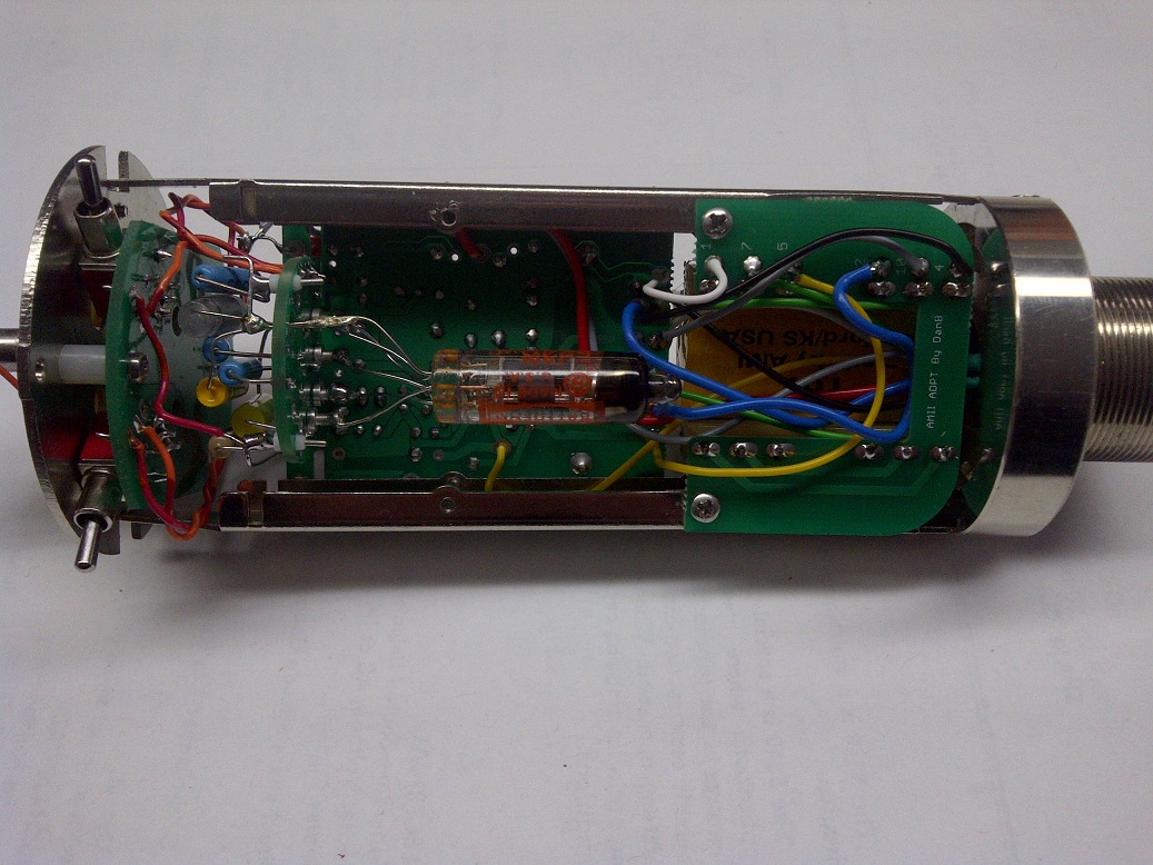
Another Piece of advice : when soldering the Tube to the Turret make sure you use the gravity in your advantage so the turret does not comes out of the hole when heating.
The Safety Manual and Considerations.https://cdn.groupbuilder.com/groupdiy/u/39511/58d1402a04d6c
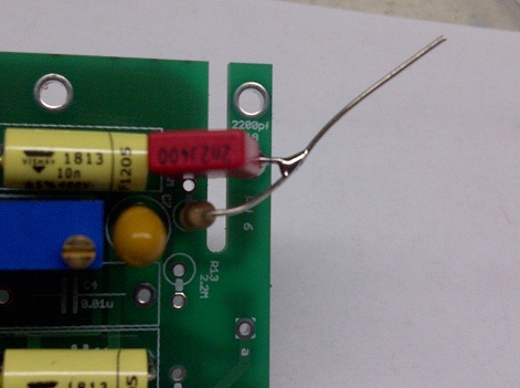
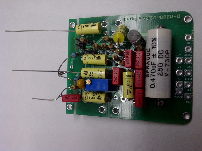
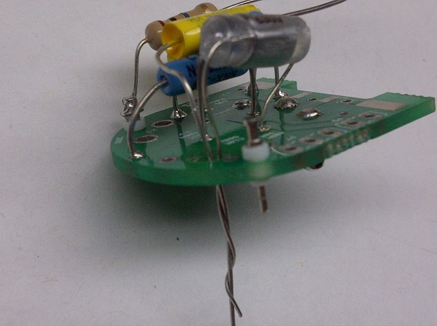
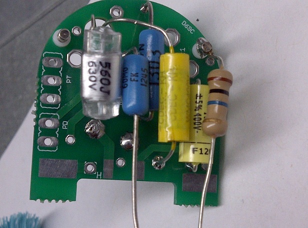
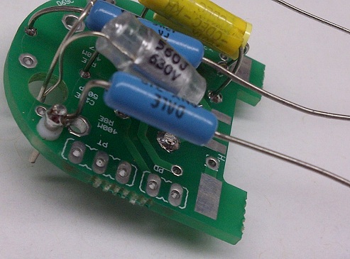
Note : Not in BOM Styroflex Capacitor 100pf/630V and Stryoflex Capacitor 270pf/630V
BOM Needed
U67 Mic part : http://www.mouser.com/ProjectManager/ProjectDetail.aspx?AccessID=83ad963d23
M269 b or C option http://www.mouser.com/ProjectManager/ProjectDetail.aspx?AccessID=6bb38c7d28
PSU : http://www.mouser.com/ProjectManager/ProjectDetail.aspx?AccessID=532017ac2f
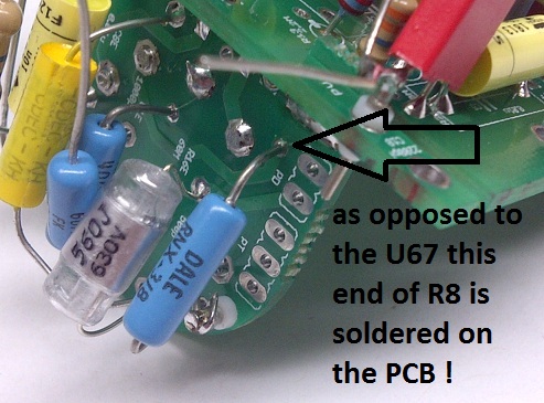
this errata also aplies to M269c please consult the U67 thread as the same correction applies,
Errata Feedback winding polarity http://groupdiy.com/index.php?topic=50021.800 reply # 814
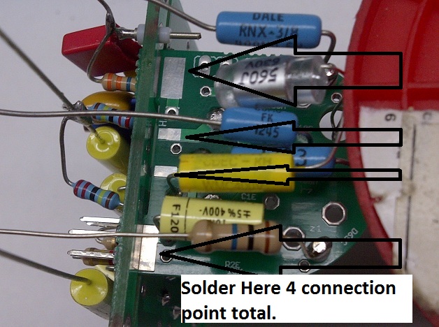
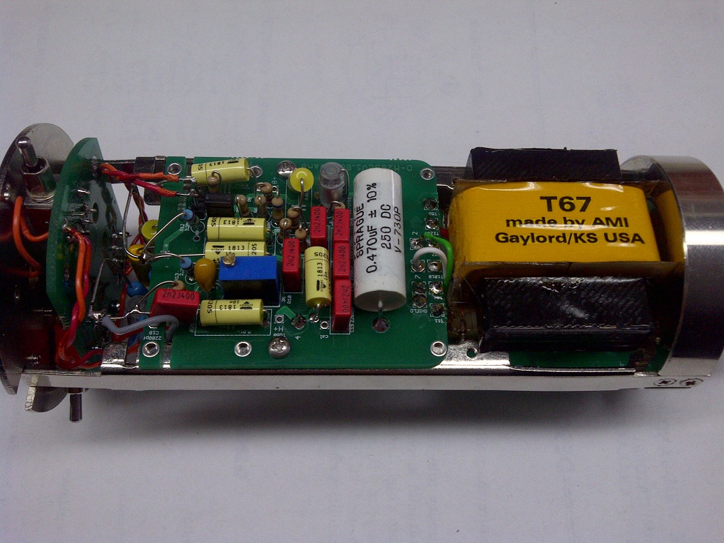
for AMI T67 only Corrected Wiring to main microphone pcb
From transformer board to mic PCB
Pad 5 -----> mic pcb pad T1212
Pad 12 -------> mic pcb pad T55
Pad 1 --------> mic pcb pad T44
Pad 4 --------> mic pcb pad T11
Pad 7 --------> mic pcb pad T1010
Pad 10 ------> mic pcb Pad T77
Wiring Guide for the M269c for pattern and Low Cut and Pad Follow the direction in this thread here they apply to both the M269b and the M269c
Right here in the Build part 2 section http://www.groupdiy.com/index.php?topic=51350.0

All of the info here : http://www.groupdiy.com/index.php?topic=49675.0
Attention R14 (plate) = 100K
Schematic Here : https://cdn.groupbuilder.com/groupdiy/u/39511/58d1402a04d0a.pdf
PSU Schematic : https://cdn.groupbuilder.com/groupdiy/u/39511/58d1402a04d18.pdf
Note : the Toroidal tranformer secondary is wired in parrallel to get 120V at the input of the psu
The 20Vac traffo for Europe will not fit as per the current BOM please replace it with this one or an equivalent ,
http://www.mouser.com/ProductDetail/Hammond-Manufacturing/186B20/?qs=sGAEpiMZZMvwUzoUXIIvyQPvPmwnNFGyR%2fQB%252b1BzrOY%3d
also The fuse will be 0.1A instead of 0.2 for America
IMPORTANT:
You Should always have the SHLF Jumper in position in the PSU PCB , this will ensure that your cable shield is tied at both end of the cable and connect to 0V
you Should Also have the 0V star grounded to your case and then from there to you IEC earth ground ,
For More Information on Grounding
https://www.dropbox.com/s/6y121dasm3iw4ba/Sound_System_Interconnection.pdf?dl=0
Cabling connection From PsU https://cdn.groupbuilder.com/groupdiy/u/39511/58d1402a04d39.jpg
D-M269C Overall Connection : https://cdn.groupbuilder.com/groupdiy/u/39511/58d1402a04d5c.jpeg
Another Piece of advice : when soldering the Tube to the Turret make sure you use the gravity in your advantage so the turret does not comes out of the hole when heating.
The Safety Manual and Considerations.https://cdn.groupbuilder.com/groupdiy/u/39511/58d1402a04d6c
Note : Not in BOM Styroflex Capacitor 100pf/630V and Stryoflex Capacitor 270pf/630V
BOM Needed
U67 Mic part : http://www.mouser.com/ProjectManager/ProjectDetail.aspx?AccessID=83ad963d23
M269 b or C option http://www.mouser.com/ProjectManager/ProjectDetail.aspx?AccessID=6bb38c7d28
PSU : http://www.mouser.com/ProjectManager/ProjectDetail.aspx?AccessID=532017ac2f
this errata also aplies to M269c please consult the U67 thread as the same correction applies,
Errata Feedback winding polarity http://groupdiy.com/index.php?topic=50021.800 reply # 814
for AMI T67 only Corrected Wiring to main microphone pcb
From transformer board to mic PCB
Pad 5 -----> mic pcb pad T1212
Pad 12 -------> mic pcb pad T55
Pad 1 --------> mic pcb pad T44
Pad 4 --------> mic pcb pad T11
Pad 7 --------> mic pcb pad T1010
Pad 10 ------> mic pcb Pad T77
Wiring Guide for the M269c for pattern and Low Cut and Pad Follow the direction in this thread here they apply to both the M269b and the M269c
Right here in the Build part 2 section http://www.groupdiy.com/index.php?topic=51350.0
") , can i take my promised break then 8),
, can i take my promised break then 8),