NEW PREAMP! X-12 Mic Preamp

GroupDIY Audio Forum

Help Support GroupDIY Audio Forum:

This site may earn a commission from merchant affiliate links, including eBay, Amazon, and others.

owel

Well-known member
Joined
Jun 3, 2004
Messages
1,088
Location
Nashville, USA
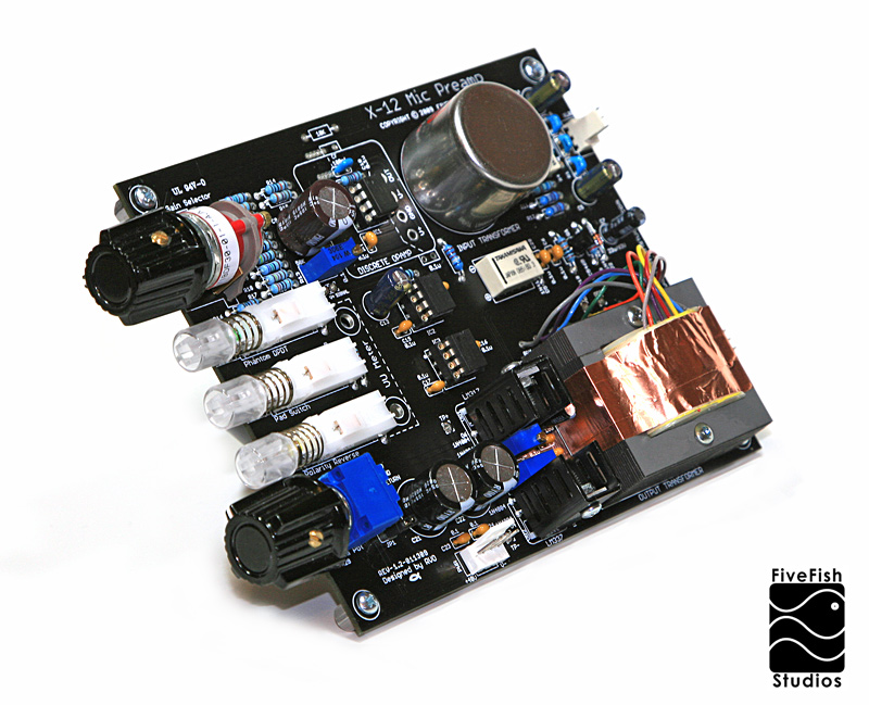
3315038044_8e121f1b90_o.jpg


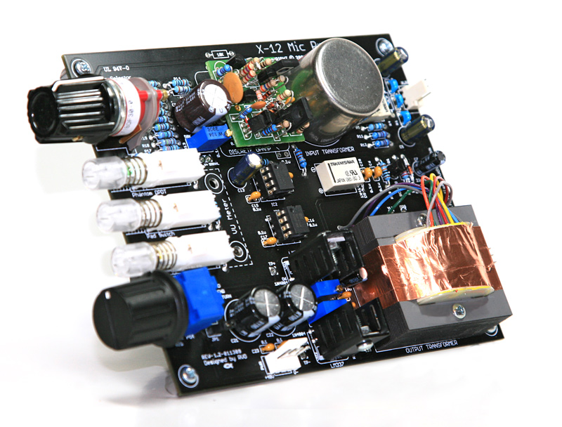
This preamp was inspired by A certain Preamp Indeed!

But no, it's not a clone.  Rather, I'd like to call it my FiveFish version :)

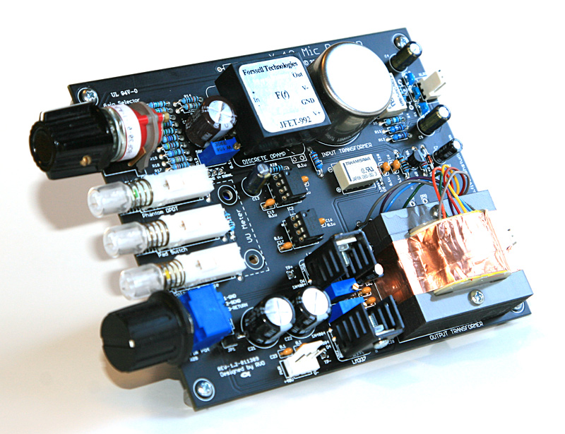
It uses input transformers with high-nickel and mumetal shielding, monolithic opamps and also has the option to use 990/992/2520 discrete opamps, null offset, output transformers, on-board voltage regulators, Relay-controlled -20dB Pads and Polarity Reverse, Soft-start phantom power, LED-lighted push button swithes, Grayhill selector switch, Bourns pot. 

The sound is huge and beefy... it will fight back when pushed hard, and slap you up and down silly to let you know who's boss... kinda like a rock n roll club bouncer.

(VU meter not shown in above photo, 5-LED VU Metering included in kit.)
 
Owel,

Nice looking preamp!

Are the card dimensions such that it is possible to mount on a 500 series L-Bracket and use an add on Roger Foote 15 pin edge connector to put in a 500 series Rack?

What is the voltage trim range for the regulators?

Are the other op-amp ICs (non-DOA footprint) used as buffers around the Trim control?

What is the target cost for the kit?

thanks!

audiohammer
 
Thanks for the compliments.

The length of the PCB is too long to use with an adapter and still allow insertion to an API lunchbox.  I specifically designed this for a 1u rack mount case. But the dimensions are close to a 500 version to allow for easy revision.

I'll have a 500 version coming soon... without the on-board voltage regulator section.  That one will have the gold fingers and be lunchbox ready, with CNC milled and engraved front panel plates, knobs, etc...

The regulators I have it set for +/-18V but it can go up to +/-24V.
But there are other chips being powered on the board, that has max +/-18 supply. So I recommend staying at +/-18V.

The other chips are used as buffers and line drivers.

My goal here is not yet another API clone using DOA (there's already lots of those around), but give the user the option to use modern (and I personally think better performing) PDIP chips we have nowadays... i.e. who wants to spend $40-$80 just for a single discrete opamp? I don't know, maybe I'm the only one that feels this way about DOA.

... OK, But since I'm at it anyway, and there's enough area on the board, I added sockets for a DOA.

Target cost: TBD.
 
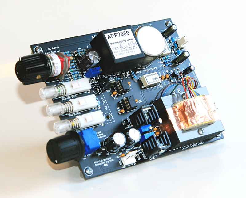
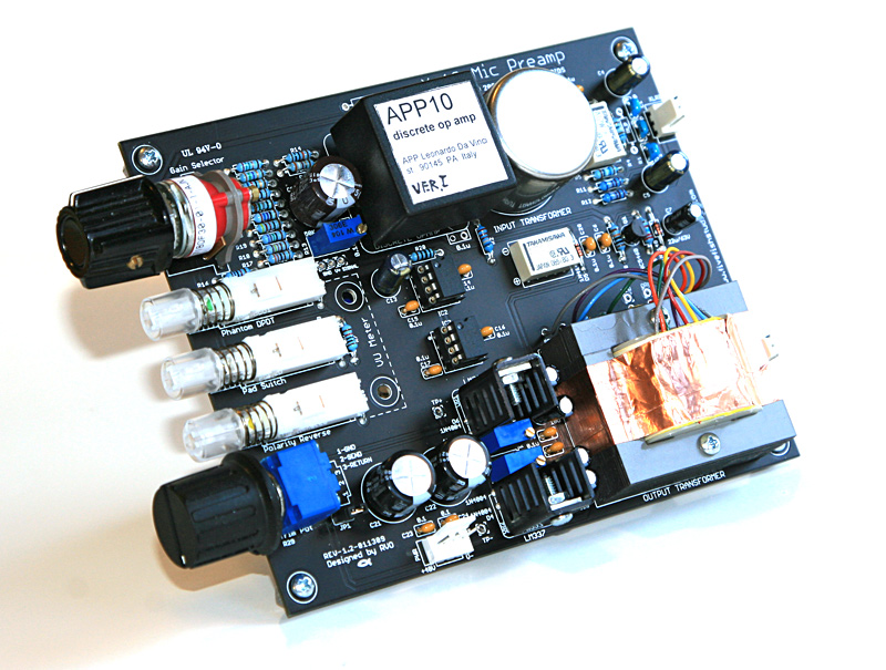
More photos showing discrete opamps installed on the board. You don't need to desolder the 8pin IC socket. Just install the MillMax sockets and the discrete opamp will install with enough cleareance above the IC socket. (You'd need to remove the PDIP8 IC chip.)

with a JFET-992
3320662474_42f85b7576_o.jpg


with APP2050 (Made in Italy)
3320662372_5c0c18072c_o.jpg


with APP10 (Made in Italy)
3320662288_43ef585588_o.jpg
 
Looks better than the real deal Owel.
Owel dont forget that DIY DOA's are about 20 bucks a kit and still cheaper if you go 1731.
Personally i think IC's sound better on a transformerless circuit than transformer in and out.
But i like the layout very much.

God bless.

 
Hey, 3nity. Thanks... I got your Yamaha DOA. I didn't know the legs are too fat to fit in the MillMax sockets. I'd probably just solder them direct to the board to try these Yamaha DOAs.  Thanks for shipping them quickly.

 
nice work Owel... looks really good. Been trying to design a slightly similar (much simpler, no 1510 or buffers, but with a 1646 output) 312 board for a friend.. taking forever at my pace though... I was trying to decide on what VU chip to use (3-5 LEDs). None seem too useful (I posted about an NTE model in the drawing board). I saw on your site that your VU board uses a 5-LED SIP 9 chip..  Is it one of those NTEs by any chance? The ones I saw have weird dB points (I basically want it to go to +3db), and I wondered if one could use just 3 (of the 5 LED) points on these chips and stick a regular diode in place of the unwanted LEDs? Is that a stupid idea? I suppose I could just leave the unwanted LEDs hidden inside the case...  Since I'll be home-etching and drilling this I want to find the less complex chips...

Don't need to share chip types and stuff if you don't want to. Just looking for some pointing in the right direction.. Thanks!
 
mitsos, yes I'm using NTE chips.  (keeping it simple for kits). But they're hard to find, always seem to be out of stock. I purchased a big lot but when that stock runs out, I may redesign my VU meters using opamps or use LM39xx chips.

if one could use just 3 (of the 5 LED) points on these chips and stick a regular diode in place of the unwanted LEDs?

I have not tried it personally, but you could try it on a breadboard.

If you'll be using 4 or less LEDs, why not just a quad opamp comparator type circuit? That way you can specifically control at what level each LED lits up?

(much simpler, no 1510 )

My X12 does not use THAT chips. They're straight opamps, compatible with a 990/2520 DOA.
 
Cool... thanks Owel.. Someone else suggested the quad comparator chip.. It seemed a bit more complex... But it may be the best way to do this and avoid things becoming obsolete.. so have to look into it...

Sorry for the 1510 confusion... I thought it was like your other boards, but makes more sense that its an opamp...

Thanks for the clarifications!
 
the comparitor i believe takes both halves of the waveform into account
and is a little more accurate than the average peak l.e.d.
 
I just looked up the comparator part in the Art of El book.. not quite there yet as far as understanding... but I'll get there....
 
Back
Top