


Hi All,
I wasn't sure if I should post this here or in Magnetics forums; The Lab seemed to be about troubleshooting so here I am")
I recently picked up a UTC A-48 Hybrid Transformer and I think it is faulty based on DC resistance measurements and trying to pass audio through it.
But since hybrid Xformers are a bit atypical and I'm fairly new to the DIY space I am hoping that you all might be able to give feedback; I don't want to contact the seller and indicate it's busted until I've exhausted all potential checks.
I tried to check historical posts here but unfortunately all the images are no longer working so I can't assess expected results. For example: UTC A-48 Hybrid Transformer
In a nutshell, there is a continuity with low ohm resistance (~0.1 Ohm) between windings that I do not think should have continuity based on the schematic present on the Xformer case. Please see below:
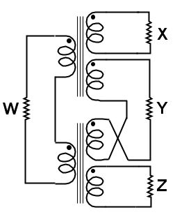
For reference here is a schematic of a Hybrid Transformer all set up for action (from wiki):
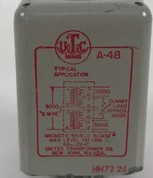
Here is the UTC A-48 schematic which indicates that all of the windings should be separated and non-conductive (the windings are within the dashed line box but the inter/intrawinding connections are outside the dashed line box):
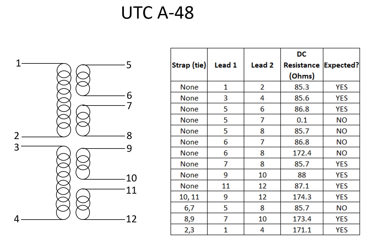
Here are my DC resistance measurements along with a more cogent schematic. To cut to the chase see the "Expected" column. It is the 5-7 connection that is baffling, and the connections associated with it. In particular the 5-8 winding connections do not respond as the 9-12 windings connections do, and the latter respond exactly as expected from the schematic.
Any pair of connections for which a resistance is not explicitly listed in the table below showed no continuity (open lead).
I'm a hare's hair away from contacting the seller for a refund unless someone can indicate that these results are somehow consistent with an intact UTC A-48 hybrid Xformer.
Thanks in advance for any thoughts.
I wasn't sure if I should post this here or in Magnetics forums; The Lab seemed to be about troubleshooting so here I am
I recently picked up a UTC A-48 Hybrid Transformer and I think it is faulty based on DC resistance measurements and trying to pass audio through it.
But since hybrid Xformers are a bit atypical and I'm fairly new to the DIY space I am hoping that you all might be able to give feedback; I don't want to contact the seller and indicate it's busted until I've exhausted all potential checks.
I tried to check historical posts here but unfortunately all the images are no longer working so I can't assess expected results. For example: UTC A-48 Hybrid Transformer
In a nutshell, there is a continuity with low ohm resistance (~0.1 Ohm) between windings that I do not think should have continuity based on the schematic present on the Xformer case. Please see below:
For reference here is a schematic of a Hybrid Transformer all set up for action (from wiki):
Here is the UTC A-48 schematic which indicates that all of the windings should be separated and non-conductive (the windings are within the dashed line box but the inter/intrawinding connections are outside the dashed line box):
Here are my DC resistance measurements along with a more cogent schematic. To cut to the chase see the "Expected" column. It is the 5-7 connection that is baffling, and the connections associated with it. In particular the 5-8 winding connections do not respond as the 9-12 windings connections do, and the latter respond exactly as expected from the schematic.
Any pair of connections for which a resistance is not explicitly listed in the table below showed no continuity (open lead).
I'm a hare's hair away from contacting the seller for a refund unless someone can indicate that these results are somehow consistent with an intact UTC A-48 hybrid Xformer.
Thanks in advance for any thoughts.
