Hey Folks -
Having trouble figuring this out. I can't find a schemo online.
Here's what I do know:
The pedal passes signal both on and off.
The Intensity and Volume pots both seem to work.
Slope and Speed don't seem to do anything.
If I come down the ribbon cable from the Speed pot with my circuit tester I get some almost clicking that changes with the rotation of that pot - giving me the speed of the tremolo...
I'm kind of lost further than this.
Thanks in advance,
Gus
Cape Breton, Canada
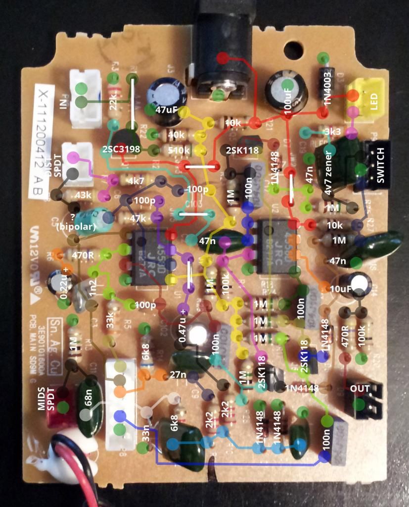
") Schematics for this particular unit seem to be unavailable, and since i'm no mind-reader, i have no idea what circuitry's in there
Schematics for this particular unit seem to be unavailable, and since i'm no mind-reader, i have no idea what circuitry's in there