The benefit of Covid19 shutting everything down is a dropoff in build/repair work, so I can get to projects that I've put off.
Next up in this CJ-inspired series of dismemberments is the Opamp Labs 325 Equalization Amplifier. A couple of people asked about this one when I did the 425 deconstruction many moons ago, here: https://groupdiy.com/index.php?topic=69637.0. I’d been curious about this unit for a long time too.
(In addition to the 325 eq amp, I also tore up a non-working 360BM mic preamp. Next post will be on that. Also planning on looking at the Model 37 limiter module. OAL also made a 325L Limiter module, but I’ve never come across one. So the 37 will have to do.)
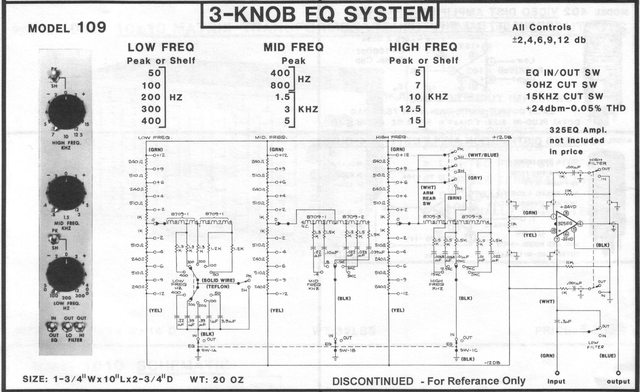
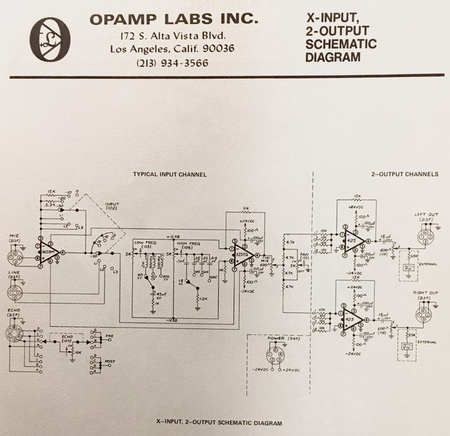
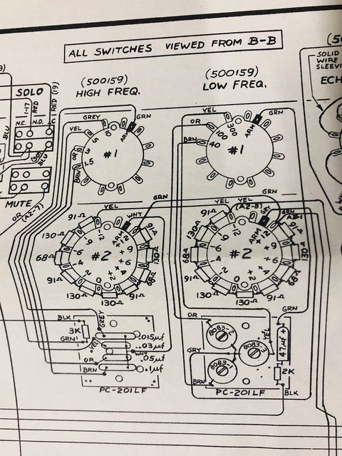
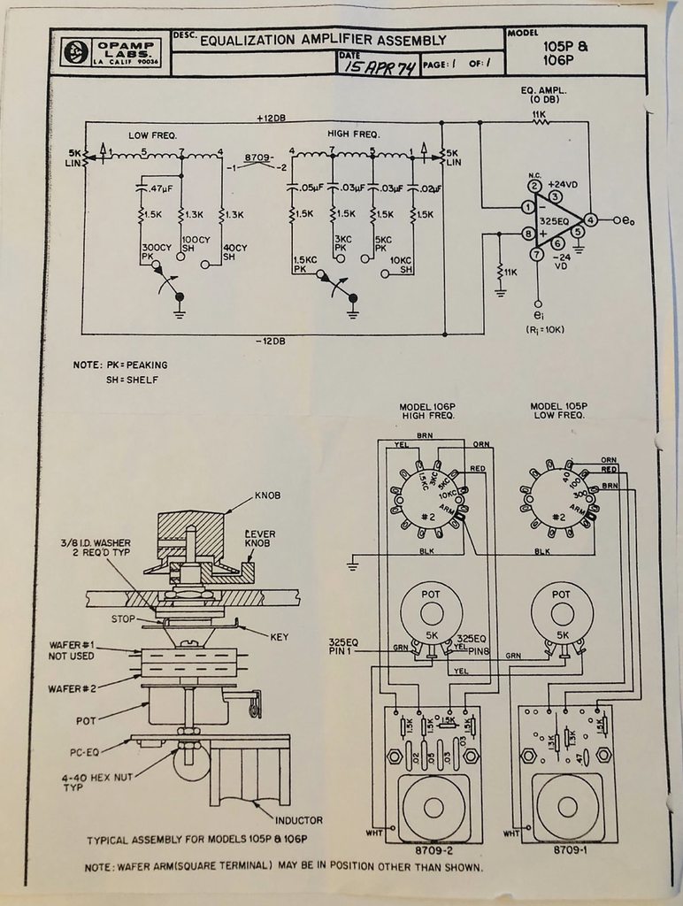
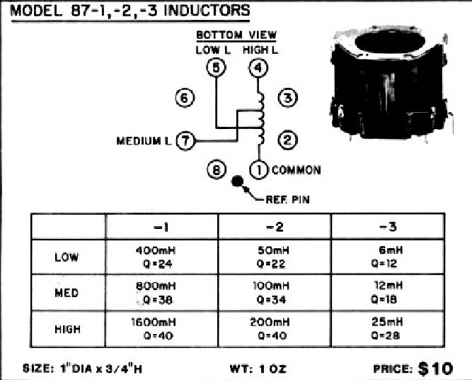
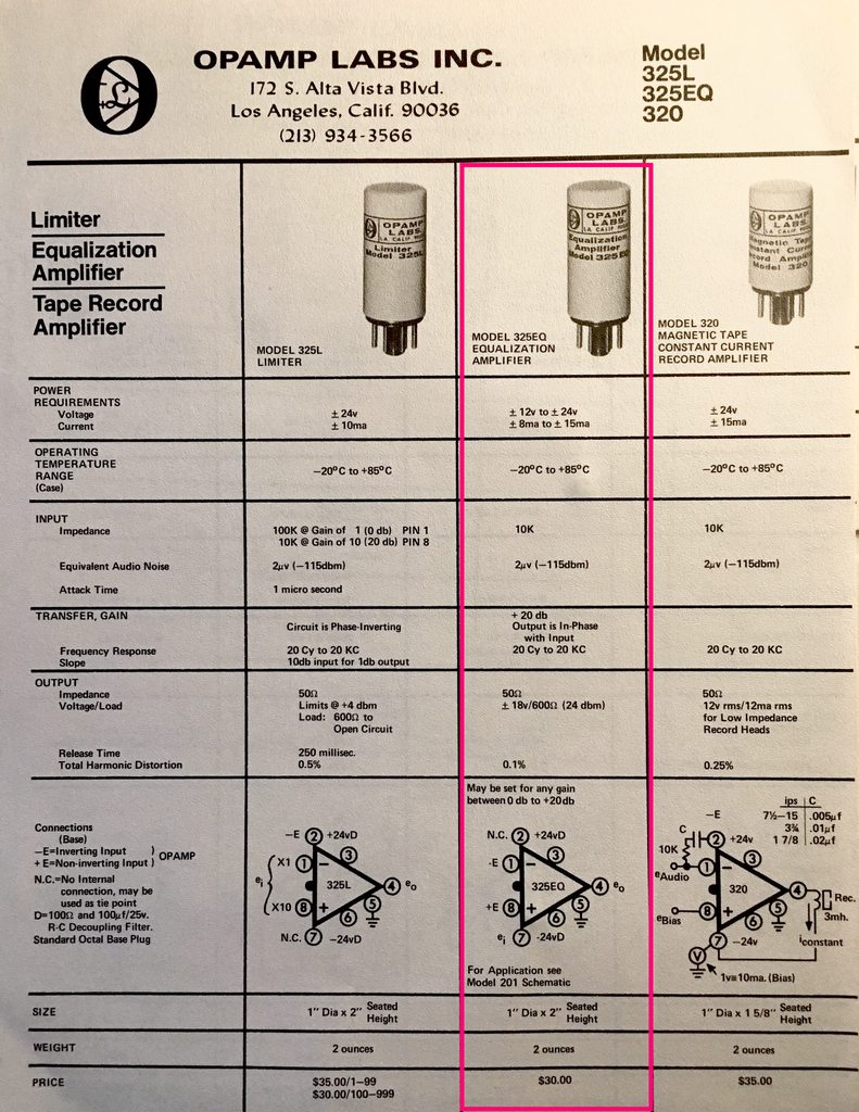
Here’s some older documentation on the 325. This is from a 1974 binder of OAL stuff.
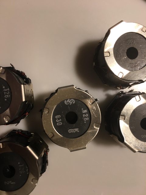
One thing that’s become clear having dissected a few of these is that starting with the torch is a mistake. When you heat the can and slide the potted board out, it tends to crumble and tear into pieces, unlike a transformer. Best way to get into these things with the guts intact is to cut the mumetal shield off completely, then use the heat gun and a very small tipped common screwdriver to pry off the potting epoxy bit by bit.
When you get the can off, you end up with this:
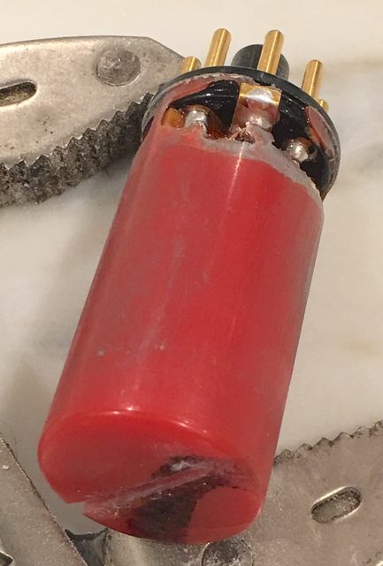
Whatever thermoset they used, it’s excellent for the task. Hard as a rock and nearly impervious to heat.
Once through the tedious task of removing as much potting junk as possible, it’s clear that this thing is a 425 on a longer PCB with a few differences in the passive components. Nothing more.
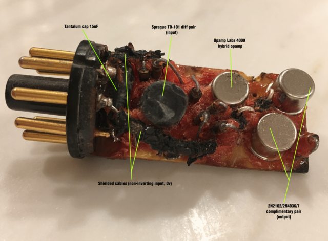
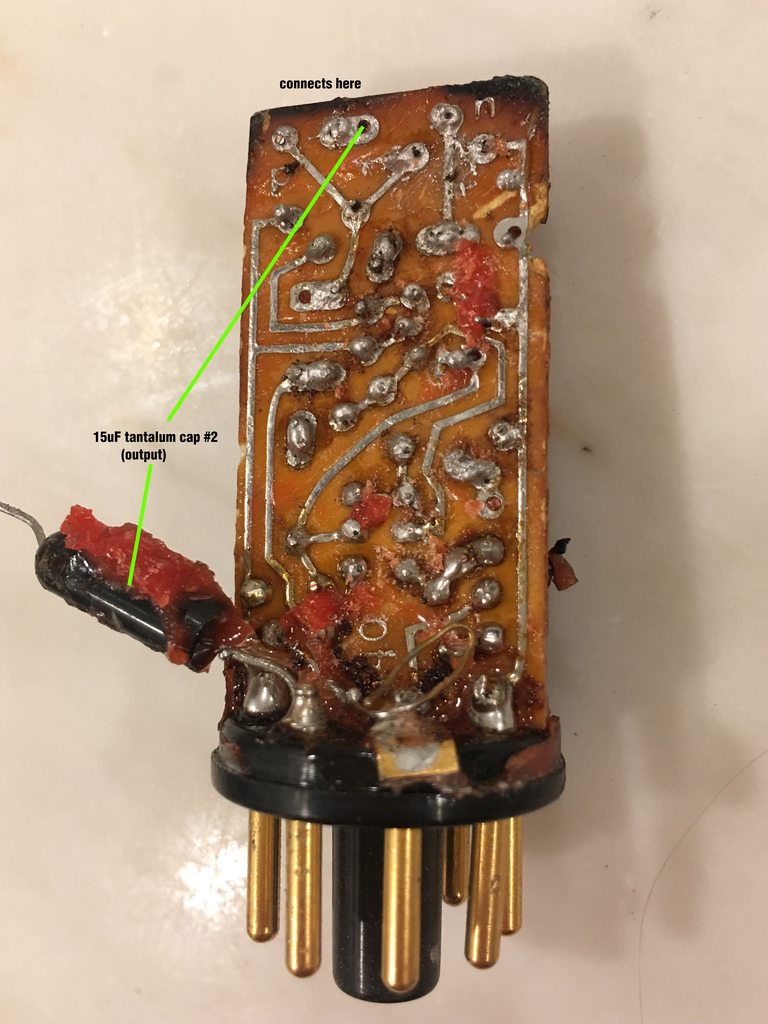
The differences between this board and the one out of the 425:
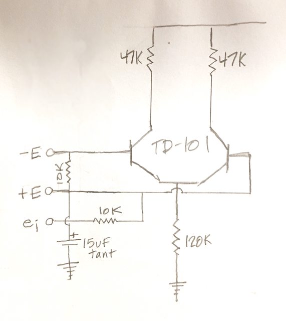
2 10k resistors on the inputs (see diagram below)
1 15uF tantalum capacitor to ground at the input (see diagram)
1 15uF tantalum coupling cap on the output (the 425 has no coupling cap on the output)
Shielded cables for the inverting and non-inverting inputs to their attachment points on the board
The pink crap was hard to get off to the point where not all component values could be identified by printed value. I was able to pull a couple of key resistors that the stripes had melted/got scraped off of and measure them though.
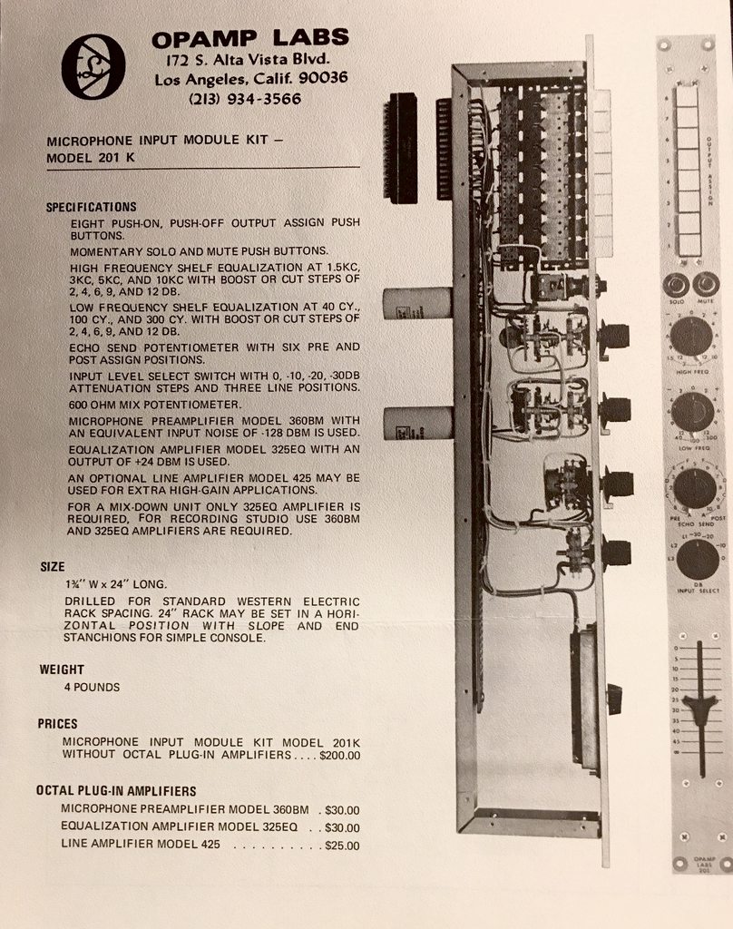
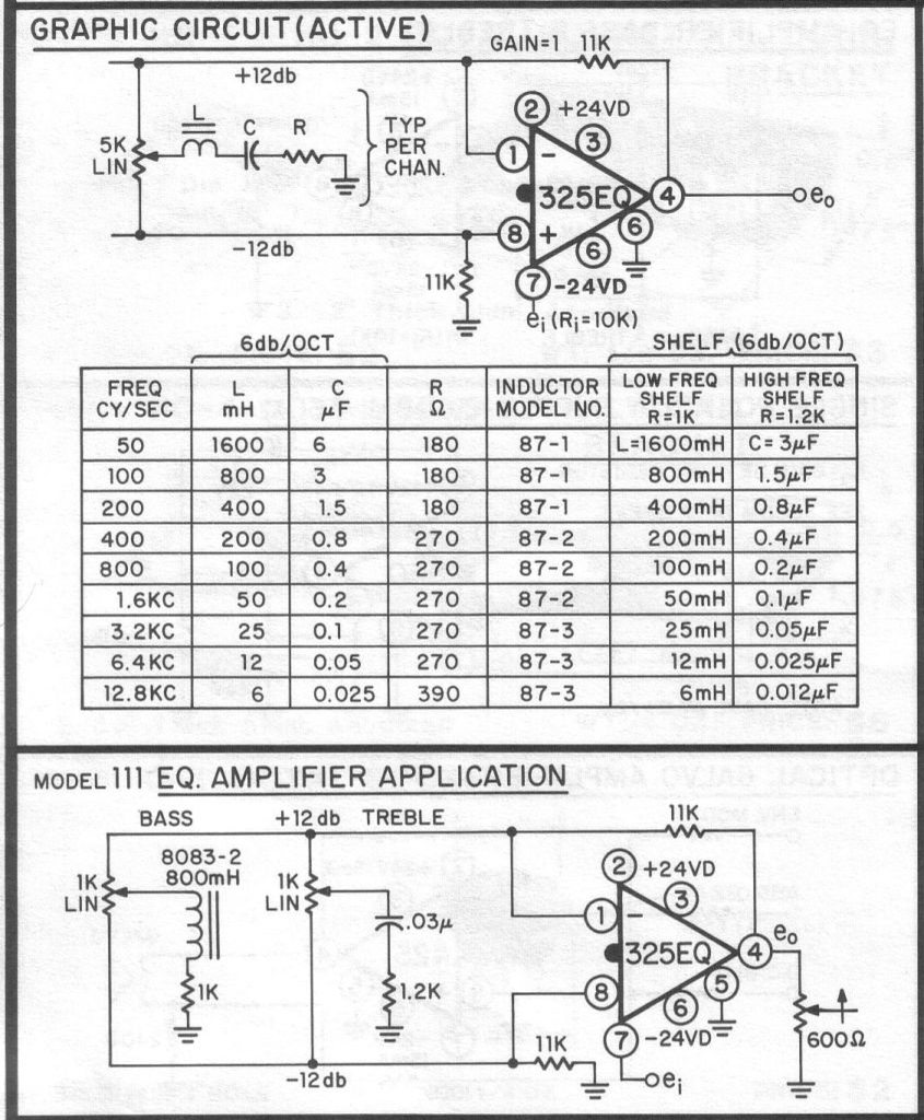
Now, the irony of all this work is that I came across the text snippet below from a Model 201 console channel kit AFTER I shortened my life breathing in the alien technology super-thermoset fumes doing this teardown! Don’t go to Vegas with me. The bright side is that it gives a better explanation of the circuit than I would have:
What I was able to trace out on the input:
And from the belatedly discovered f*$%in’ manual:
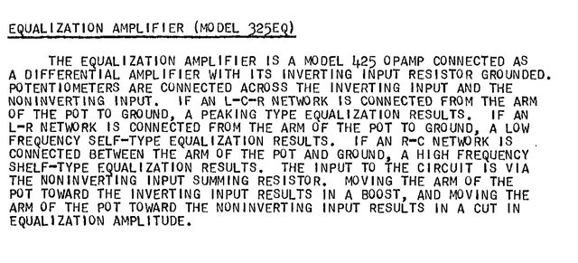
The explanation above should tell you what you need to know to use this thing, but next post I'll outline the rest of what I found researching it. There are at least a couple of designs worth playing with that you could start from.
Next up in this CJ-inspired series of dismemberments is the Opamp Labs 325 Equalization Amplifier. A couple of people asked about this one when I did the 425 deconstruction many moons ago, here: https://groupdiy.com/index.php?topic=69637.0. I’d been curious about this unit for a long time too.
(In addition to the 325 eq amp, I also tore up a non-working 360BM mic preamp. Next post will be on that. Also planning on looking at the Model 37 limiter module. OAL also made a 325L Limiter module, but I’ve never come across one. So the 37 will have to do.)
Here’s some older documentation on the 325. This is from a 1974 binder of OAL stuff.

One thing that’s become clear having dissected a few of these is that starting with the torch is a mistake. When you heat the can and slide the potted board out, it tends to crumble and tear into pieces, unlike a transformer. Best way to get into these things with the guts intact is to cut the mumetal shield off completely, then use the heat gun and a very small tipped common screwdriver to pry off the potting epoxy bit by bit.
When you get the can off, you end up with this:

Whatever thermoset they used, it’s excellent for the task. Hard as a rock and nearly impervious to heat.
Once through the tedious task of removing as much potting junk as possible, it’s clear that this thing is a 425 on a longer PCB with a few differences in the passive components. Nothing more.


The differences between this board and the one out of the 425:
2 10k resistors on the inputs (see diagram below)
1 15uF tantalum capacitor to ground at the input (see diagram)
1 15uF tantalum coupling cap on the output (the 425 has no coupling cap on the output)
Shielded cables for the inverting and non-inverting inputs to their attachment points on the board
The pink crap was hard to get off to the point where not all component values could be identified by printed value. I was able to pull a couple of key resistors that the stripes had melted/got scraped off of and measure them though.
Now, the irony of all this work is that I came across the text snippet below from a Model 201 console channel kit AFTER I shortened my life breathing in the alien technology super-thermoset fumes doing this teardown! Don’t go to Vegas with me. The bright side is that it gives a better explanation of the circuit than I would have:
What I was able to trace out on the input:

And from the belatedly discovered f*$%in’ manual:

The explanation above should tell you what you need to know to use this thing, but next post I'll outline the rest of what I found researching it. There are at least a couple of designs worth playing with that you could start from.


