midwayfair
Well-known member
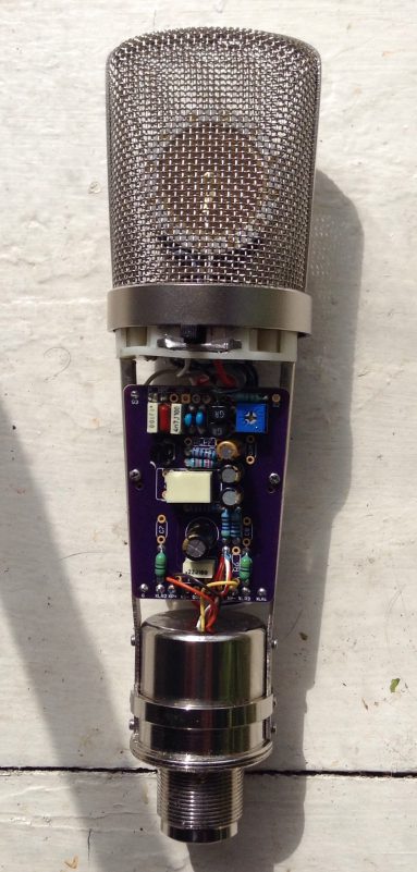
This is a PCB set meant to replace the circuitboards in inexpensive transformer-coupled microphones that use a FET + emitter follower circuit and a low ratio (almost always 2:1) transformer. Usually the transformer is actually fine though I will say I do generally prefer the sound of the Cinemag.
This project is a lot less generic than the Schoeps-style transformerless mic board was, so I'll explain all the changes real quick:
First, like the Schoeps board, I've made the assumption that you are going to be using a flatter-response capsule than the typical 67-style capsule in an off-the-shelf mic or in the Aurycle kits, mainly because that tends to be the first thing people modify. For this reason, I chose to omit the u87-style negative feedback circuit. It doesn't have that big of an effect and I've never had any particular luck with it anyway -- removing it from my aurycle build killed a good 3-6dB of white noise (not just better S:N). It was also quite a few extra parts to fit, and without standing resistors (ew) it would have meant sacrificing some of the more important changes, like an improved power filtering chain.
I did, however, manage to shoe-horn in a simpler low-pass shelf filter on these PCBs for use in a pinch if you aren't replacing the capsule. It's three fewer parts but it's similar to what's used in some C12/ELA251 projects that put a pF capacitor from the plate to ground. See the notes on the schematic for suggested starting points -- 470pF and 10K would put it -4.5dB centered around 10KHz (the cutoff would go up if the FET's output impedance is lower than 33K, so using a different FET changes things).
I made a few tweaks to the circuit, lowering the current draw of the audio stages and including extra power filtering stages for both transistors.
There are components for a switched high pass filter and a negative feedback pad like in the KM84, both with optional parts to be used with on-off-on switches (which requires some creativity in getting them into the microphone body ...).
Finally, I included one of my favorite modifications, which is optional parallel FETs for the input device.
Project background:
As MXL and other manufacturers selling basically the same product move to SMD, it's harder and harder to find a mic that can just be straight-up modded, and for the most part I don't think the PCB sellers on here are going to be very interested in making a project for sale that's a copy of a dirt-cheap mic.
These PCBs are fitted to the body that's used in the V63/V67 (and the numerous similar mics by Thomann etc), Aurycle (IMO the best completely blank bodies you can get for this size - unpainted but heavy brass), BM800 (I believe that's the same body shape and size), etc.
Standard warning:
******These documents may change until they are verified by both me and at least one other user!******
This is a work in progress -- I am going to make the PCB order this weekend, though, so I'll be able to test all the open source project PCBs at once.
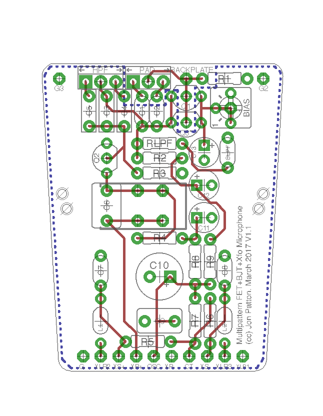
Schematics and layouts:
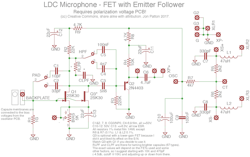
This one requires a polarization PCB. You can go hardcore and make it on perfboard like Audioimprov, or I've shared some on Osh Park, which can find in this thread: https://groupdiy.com/index.php?topic=65174.0
Osh Park share: https://oshpark.com/shared_projects/pOLxStQo
Mouser cart: http://www.mouser.com/ProjectManager/ProjectDetail.aspx?AccessID=c47896c57b
An explanation of some of the notes on the BOM:
1. There is a 2n3819 in the cart in case you simply can't get ahold of a 2SK30, 2SK170, or any similar FETs (e.g. 2N5457, 2N5485, 2N5952, BF245, etc. -- all of which have different pinouts but will work fine).
2. There are some alternate parts if you're building with a 4:1 transformer instead of a 2:1. (Cinemag sells both.) For instance a smaller output capacitor (2u2 instead of 4u7) and a 22K for the Q2 emitter resistor instead of 10K.
3. There is a multiturn or single-turn trim, your choice, for the bias voltage. Both will fit on the PCB.
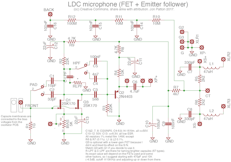
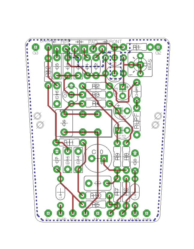
This one has on-board polarization. It's basically me getting all the parts I actually use from the Aurycle kit (which is the same as the MXL V67G) onto a single PCB. The polarization is lifted from the KM84. You only get ~40V on the capsule (the audio path sags the phantom power some even with the current draw lowered) but that's plenty good enough for single-pattern.
Osh Park share: https://oshpark.com/shared_projects/dV2qXGta
Mouser cart: http://www.mouser.com/ProjectManager/ProjectDetail.aspx?AccessID=fa56fe3804
Same notes as above about the Mouser cart apply here.
If you need a transformer, like if you're buying the Aurycle body by itself instead of modding an existing mic, Cinemag's CM-11021 and CM-24110 are both solid choices.
Technically you could build either of these with a higher-ratio transformer. But Dan has a better project PCB for that (the D847), and that's getting farther and farther away from the point of the project.
After I've verified the layout, if anyone wishes I can share the Eagle files.
This project is a lot less generic than the Schoeps-style transformerless mic board was, so I'll explain all the changes real quick:
First, like the Schoeps board, I've made the assumption that you are going to be using a flatter-response capsule than the typical 67-style capsule in an off-the-shelf mic or in the Aurycle kits, mainly because that tends to be the first thing people modify. For this reason, I chose to omit the u87-style negative feedback circuit. It doesn't have that big of an effect and I've never had any particular luck with it anyway -- removing it from my aurycle build killed a good 3-6dB of white noise (not just better S:N). It was also quite a few extra parts to fit, and without standing resistors (ew) it would have meant sacrificing some of the more important changes, like an improved power filtering chain.
I did, however, manage to shoe-horn in a simpler low-pass shelf filter on these PCBs for use in a pinch if you aren't replacing the capsule. It's three fewer parts but it's similar to what's used in some C12/ELA251 projects that put a pF capacitor from the plate to ground. See the notes on the schematic for suggested starting points -- 470pF and 10K would put it -4.5dB centered around 10KHz (the cutoff would go up if the FET's output impedance is lower than 33K, so using a different FET changes things).
I made a few tweaks to the circuit, lowering the current draw of the audio stages and including extra power filtering stages for both transistors.
There are components for a switched high pass filter and a negative feedback pad like in the KM84, both with optional parts to be used with on-off-on switches (which requires some creativity in getting them into the microphone body ...).
Finally, I included one of my favorite modifications, which is optional parallel FETs for the input device.
Project background:
As MXL and other manufacturers selling basically the same product move to SMD, it's harder and harder to find a mic that can just be straight-up modded, and for the most part I don't think the PCB sellers on here are going to be very interested in making a project for sale that's a copy of a dirt-cheap mic.
These PCBs are fitted to the body that's used in the V63/V67 (and the numerous similar mics by Thomann etc), Aurycle (IMO the best completely blank bodies you can get for this size - unpainted but heavy brass), BM800 (I believe that's the same body shape and size), etc.
Standard warning:
******These documents may change until they are verified by both me and at least one other user!******
This is a work in progress -- I am going to make the PCB order this weekend, though, so I'll be able to test all the open source project PCBs at once.
Schematics and layouts:
This one requires a polarization PCB. You can go hardcore and make it on perfboard like Audioimprov, or I've shared some on Osh Park, which can find in this thread: https://groupdiy.com/index.php?topic=65174.0
Osh Park share: https://oshpark.com/shared_projects/pOLxStQo
Mouser cart: http://www.mouser.com/ProjectManager/ProjectDetail.aspx?AccessID=c47896c57b
An explanation of some of the notes on the BOM:
1. There is a 2n3819 in the cart in case you simply can't get ahold of a 2SK30, 2SK170, or any similar FETs (e.g. 2N5457, 2N5485, 2N5952, BF245, etc. -- all of which have different pinouts but will work fine).
2. There are some alternate parts if you're building with a 4:1 transformer instead of a 2:1. (Cinemag sells both.) For instance a smaller output capacitor (2u2 instead of 4u7) and a 22K for the Q2 emitter resistor instead of 10K.
3. There is a multiturn or single-turn trim, your choice, for the bias voltage. Both will fit on the PCB.
This one has on-board polarization. It's basically me getting all the parts I actually use from the Aurycle kit (which is the same as the MXL V67G) onto a single PCB. The polarization is lifted from the KM84. You only get ~40V on the capsule (the audio path sags the phantom power some even with the current draw lowered) but that's plenty good enough for single-pattern.
Osh Park share: https://oshpark.com/shared_projects/dV2qXGta
Mouser cart: http://www.mouser.com/ProjectManager/ProjectDetail.aspx?AccessID=fa56fe3804
Same notes as above about the Mouser cart apply here.
If you need a transformer, like if you're buying the Aurycle body by itself instead of modding an existing mic, Cinemag's CM-11021 and CM-24110 are both solid choices.
Technically you could build either of these with a higher-ratio transformer. But Dan has a better project PCB for that (the D847), and that's getting farther and farther away from the point of the project.
After I've verified the layout, if anyone wishes I can share the Eagle files.
 I've had a set of boards done a while ago (10 of each), just haven't quite gotten around to completing (ie. assembling) a set of each just yet, though. Life keeps getting in the way, and all that