I have a quick question about adding an output level attenuator like my Neve 1272 preamps have for the API preamp card. Is it better to add the volume pot post preamp circuit but BEFORE the output transformer, or will it be better to add a dual ganged pot AFTER the transformer to equally attenuate the + and - outs of the transformer prior to the output jack? Obviously, before the transformer means using a standard 3 pin audio taper pot that bleeds off a portion of the signal to ground and is a much more readily available and cheaper approach. But it seems like the loading of the output transformer in conjunction with the preamp circuit output may be more beneficial soundwise to bleed off the signal after the transformer. I was curious what others thought about this and whether it matters. Basically I want the ability to overdrive the amp circuit a bit before output, and the pot is a way to keep the signal level manageable for input into my recorder while still taking advantage of the (nice) distortion that would occur from hitting the amplifier circuit a little hot.
You are using an out of date browser. It may not display this or other websites correctly.
You should upgrade or use an alternative browser.
You should upgrade or use an alternative browser.
Output level attenuator for API 312 amp circuit
- Thread starter druedger
- Start date


Help Support GroupDIY Audio Forum:
This site may earn a commission from merchant affiliate
links, including eBay, Amazon, and others.
okgb
Well-known member
it is often hard to find dual pots that track well
so you risk losing some common mode rejection
into the next device
switched resisters once you find the right value
may work better as an output att.
so you risk losing some common mode rejection
into the next device
switched resisters once you find the right value
may work better as an output att.
Sleeper
Well-known member
Seems like a balanced H or U pad after the transformer would do what you need. 3 steps is probably even overkill if you can do what OKGB says, overcrank the API for the distortion you want and figure out how much you need to drop to be safe on your input levels for the next stage.
there are some cool calculators online to figure out the values you need.
Sleeper
there are some cool calculators online to figure out the values you need.
Sleeper
Check the 312 info in the META. I remember that someone posted a great stepped attenuator for the 312. I have not looked for it since the forum changeover.
Mike
Mike
peter purpose
Well-known member
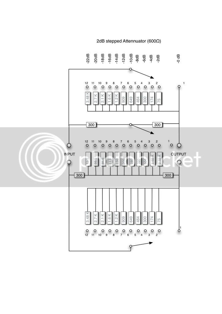
This one?

TomWaterman
Well-known member
druedger said:Is it better to add the volume pot post preamp circuit but BEFORE the output transformer
Placing a pot at the opamp output before the transformer is a bad plan as the output Z of the pot in certain positions will end up so high the transformer will produce unwanted distortion. Transformers like to fed from a low source Z.
A switched H-pad at the output, maybe 600 ohms (which I guess is what Peter just posted) would be nice.
You don't need many steps to pad it down if all your after is serious preamp overdrive.
-T
This may not be the audiophile way but it works just fine and is cheap. Get a 1K audio log pot and strap across the transformer hi and lo outputs.
Straight from the API playbook. This is what they did on the 827 Master Cue Amps.
Cheers, Jeff
Straight from the API playbook. This is what they did on the 827 Master Cue Amps.
Cheers, Jeff
Sarcastic Sound
Well-known member
I've never had an Alps dual pot that was intolerable between each deck. last one I installed had 1.8 ohms difference between each deck at maximum resistance (10k pot)... I'd go for attenuation after the tranny with an Alps or comparable high quality dual pot to bring your signal down and drive your API into harmonic saturation submission ;D
plumsolly
Well-known member
Ive done three 6db steps after the output transformer with great success. just a bridged-t on a breadboard with a lorlin 4-position, 3-pole, rotary switch. 0, -6, -12, -18db. I used this schematic (thanks to whoever made this - I think it was someone on this forum):
also check out this link for basic info on pads - http://www.uneeda-audio.com/pads/
edit: I reposted this part in another thread:
On a related note - I've been thinking about a basic attenuator pcb that could be stuffed for any amount of attenuation in up to twelve steps (or maybe even 24) at whatever input and output impedance you chose and would fit a greyhill or lorlin pcb-mount switch. It would be a bridged-t attenuator. It seems like it would be really handy for a number of applications like this one or even a (way-less-cool-and-useful-than-Igor's) rudimentary monitor controller (obviously this would require a pair or a 2 deck switch wired to two boards) you could also experiment with driving your consoles two-buss a bit or whatever else. I'd like to have a rack of 6 or so attenuators that i could put in front of my converters to experiment with driving everything, just patch them in. chime in with your thoughts - i'll start a new thread if it gets cluttered. -Ben
saint gillis
Well-known member
jsteiger said:This may not be the audiophile way but it works just fine and is cheap. Get a 1K audio log pot and strap across the transformer hi and lo outputs.
Straight from the API playbook. This is what they did on the 827 Master Cue Amps.
Cheers, Jeff
I ve tried several things, several pads, bridged T pads etc, untill -25db, I must say the most convenient is the solution above, no problems to use a mic very close to a snare or a kick drum, great.
Will the quick, dirty pot across OT secondaries cause HF loss as a side effect ?
How about using the spare, unseries'd OT winding instead of attenuating the series'd winding ? What's the pro/con of doing it one way vs. the other?
How about using the spare, unseries'd OT winding instead of attenuating the series'd winding ? What's the pro/con of doing it one way vs. the other?
Answered here a few posts from the bottom: https://www.gearslutz.com/board/so-much-gear-so-little-time/152310-how-deal-w-lack-output-attn-api512-if-u-wanna-drive-pre-xfmr-hot.html
Anything else to add?
Anything else to add?
alternate solution-put a pot in the feedback loop
don't need stepped attenuators, dual pots, T or H bridges,
no worries about sonic effects from transformer loading,
might be some shift in tonal response which could be tweaked with a cap wired up to the pot in the right manner,
you don't need a ton of control with a mic pre, and there will always be a sweet spot on the gain setting, then just move mic around to keep the amp in the zone,
jsteiger said:This may not be the audiophile way but it works just fine and is cheap. Get a 1K audio log pot and strap across the transformer hi and lo outputs.
Straight from the API playbook. This is what they did on the 827 Master Cue Amps.
Cheers, Jeff
Hi Jeff , thanks for the cheap 1K pot tips.
Can you or someone please be kind enough to explain why this "may not be the audiophile way"? why is it sub-optimal?
What could be the practical losses or problems by doing it this way rather than using for example a 600ohm T-PAD attenuator?
thanks
ruffrecords
Well-known member
Whoops said:Can you or someone please be kind enough to explain why this "may not be the audiophile way"? why is it sub-optimal?
What could be the practical losses or problems by doing it this way rather than using for example a 600ohm T-PAD attenuator?
thanks
A lot of the 'proper' way to do this is a hangover from the old 600 ohm source and load days when everything needed to be matched. Nowadays with low impedance outputs and bridging inputs this is not necessary. The lovely 3 pole 12 way switch version posted earlier by plumsolly is a perfect example of how it 'should' be done to maintain a constant 600 ohm impedance. It is a balanced bridged T. You can do it with just two switches and make a constant impedance unbalanced bridged T and this is how all the Painton faders in the old EMI consoles were made - in other words its OK in a controlled environment over short distances.
With the 1K pot method the load impedance is fairly constant but the source impedance varies with the pot position with a maximum when the pot is close to half resistance. It is also unbalanced. With a 1K pot, the source impedance will be a lot lower than a true 600 ohm source so there is no need to worry about HF losses unless you have very long cables connected to the pot (ten of yards/metres).
The problem with a 1K pot is that the resistance is not very well controlled in manufacture (unless you pay a LOT of money for it) which means the two halves do not track very well if you make a stereo one. Just like API, we used a pot like this for a monitor level control at Neve back in the 70s. To overcome the poor tracking of audio taper pots we used a linear pot with a slugging resistor - typically a 2K pot with a 1K slug - which means the level is about 10dB down at half way.
There are ways of improving the design still further but for a monitor level control there is really no point.
Cheers
Ian
ruffrecords said:The problem with a 1K pot is that the resistance is not very well controlled in manufacture (unless you pay a LOT of money for it) which means the two halves do not track very well if you make a stereo one. Just like API, we used a pot like this for a monitor level control at Neve back in the 70s. To overcome the poor tracking of audio taper pots we used a linear pot with a slugging resistor - typically a 2K pot with a 1K slug - which means the level is about 10dB down at half way.
Hi Ian thanks for your reply.
I'm sorry but I didnt understand this section "two halves do not track very well if you make a stereo one", what does that mean?
I was asking for a single 1K Pot connected between the transformer secondaries like the pics that Jeff posted.
What would be the problems or deficiencies of that.
thanks
ruffrecords
Well-known member
Whoops said:Hi Ian thanks for your reply.
I'm sorry but I didnt understand this section "two halves do not track very well if you make a stereo one", what does that mean?
I was asking for a single 1K Pot connected between the transformer secondaries like the pics that Jeff posted.
What would be the problems or deficiencies of that.
thanks
A lot of people use something like this for a stereo monitor level control; hence my comments. For your application where you just have a single mono output then a 1K pot will work fine.
Cheers
Ian
gridcurrent
Well-known member
- Joined
- Aug 28, 2009
- Messages
- 589

Gene Pink
Well-known member
gridcurrent said:For those that believe reducing headroom is beneficial,
here is another approach.
What am I missing? For the -9dB setting, I get -6dB with reverse polarity. Are all the windings the same Z? Are all assumed to have the polarity dot at the top in the drawing?
Gene
ruffrecords said:Whoops said:Hi Ian thanks for your reply.
I'm sorry but I didnt understand this section "two halves do not track very well if you make a stereo one", what does that mean?
I was asking for a single 1K Pot connected between the transformer secondaries like the pics that Jeff posted.
What would be the problems or deficiencies of that.
thanks
A lot of people use something like this for a stereo monitor level control; hence my comments. For your application where you just have a single mono output then a 1K pot will work fine.
Cheers
Ian
Thanks you so much Ian.
So in this application is there any reason to use an expensive 600ohm T PAD over the 1K pot or practically they will both achieve the exactly same results?
Similar threads
- Replies
- 32
- Views
- 2K
- Replies
- 14
- Views
- 670