Passive riaa filter.

GroupDIY Audio Forum

Help Support GroupDIY Audio Forum:

This site may earn a commission from merchant affiliate links, including eBay, Amazon, and others.

Fredrik

Well-known member
Joined
Aug 29, 2005
Messages
115
Hi there,

Does anyone know of any passive riaa filters? You would connect the filter between a turntable and a pre-amp. I need the riaa curve to be accurate so any previous attempt would be interesting to look over. Are there any pitfalls here compared to an active filter?
 
The obvious problem with full passive is that the gain changes approc 40 dB from 20Hz to 20kHz so you could have serious headroom-S/N issues doing one completely passive.

I designed several (IMO) good preamps back when records were still the currency of the realm, and in my judgement there is some hypothetical merit to making the 75uSec pole in the RIAA playback a real pole. I would (and have) made the rest (318 uSec zero and 3180  uSec pole) active. Of course once you pass the audio through a LPF at about 2kHz even a 741 opamp can keep up with the slew rate.  8)

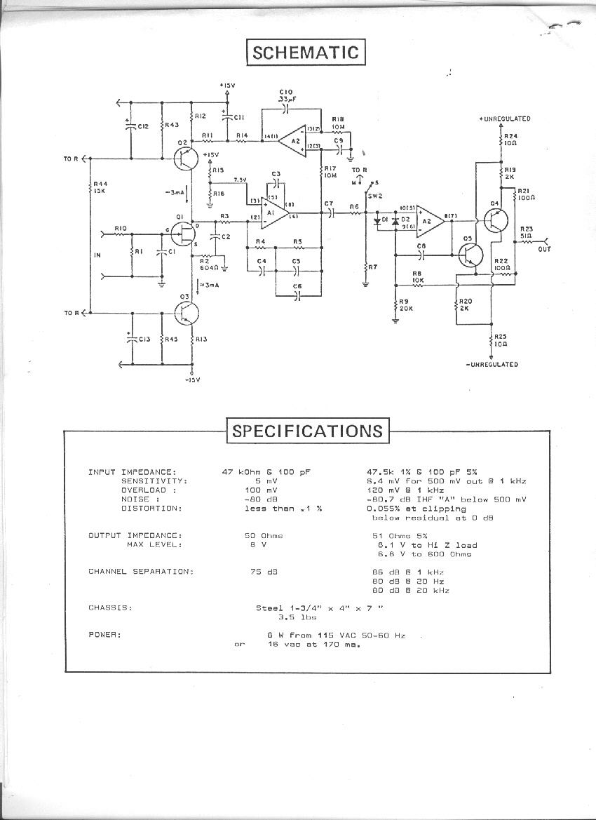
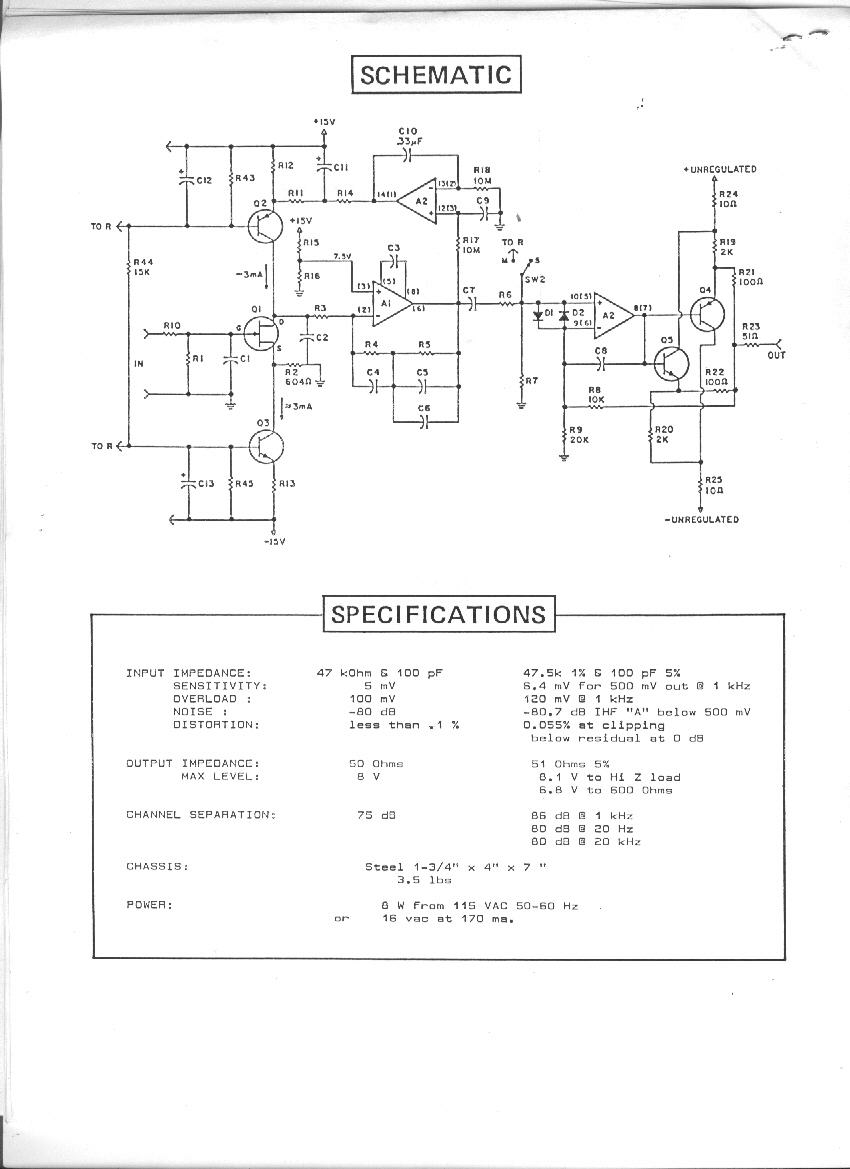
Here is a schematic for my last attempt some 25-30 years ago.  The 75 uSec pole is formed by C2 and R3, the first stage runs without negative feedback (except for the DC servo feeding the current source). The rest of the RIAA is in the feedback of A1 (used polystyrene caps).

You could hit this input stage with lightning, and the circuit wouldn't slew limit.

P100.gif

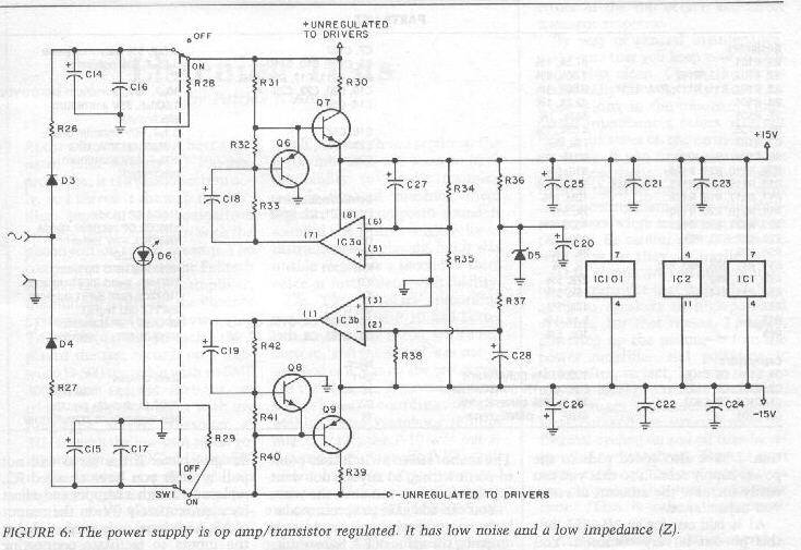
it used an external wall wart and this low noise PS
P100_PS.jpg


The output driver is a little more cute than it needed to be but it worked OK, and I actually got an OK review from one of the audiophool rags, but it wan't expensive enough for them to get really excited.

Of course this is kind of history now, while vinyl is still fashionable in some niches.

Note: This preamp actually used the NAB 7950uSec pole for LF roll-off that the tweaky reviewer actually noticed (color me impressed).

JR

PS: I used to have an passive inverse RIAA that I used for testing preamps, but it generated the mirror image of RIAA de-emphasis.


Why do you insist on passive?
Starting with 5mV, applying 30dB attenuation, you end up with -80dBu at the input of the mic pre, with a degraded source impedance. Your S/N ratio will be less than 40dB.
 
Passive phono EQ was often used in radio stations to bring mag-phono into mike inputs. S/N was not a serious problem. They may have been inductor-based.

 
Hagerman has a passive EQ design BUT the EQ stages are split between three buffer/amplifier stages.
http://www.hagtech.com/images/bugleschem.gif

The attached scheme appears to implement RIAA well with nearly mag-phono suitable input loading. The rise in Zin below 80Hz could cause a mild bass rise. A 140H(!) 47K inductor across the input would fix this. Loss is BIG.
 

Attachments

  • pass-RIAA.gif
    pass-RIAA.gif
    14.4 KB
Yup there were several "split EQ" design approaches back in the day, where a fixed gain stage, was followed by a EQ often passive as shown, and some final make up gain. I'm not sure why exactly, I guess there was a religious belief that NF was bad, and less bad if making flat gain. Ironically that isn't true but (Yawn) phono preamp circuitry was so far beyond the capability of the mechanical system we were all chasing the angel's footsteps on the pinhead, to do something different.

I did a preamp back several years before the one I posted above, where I used a flat gain stage in the front end, and configured my RIAA in a combination input/feedback network of an inverting opamp. (I also offered a version with low noise bipolar front end, with more gain for lower impedance/output MC cartridges).

Not to poke a sharp stick at the NFB is bad crowd, by putting the 3180 uSec pole in the NF network around a TL07x gave me beaucoup loop gain margin across the entire band. IMO superior to passive EQ with flat make up gain, unless the goal is something other than accuracy and precision.

P10.gif


This dealt with one of my criticisms of the common non-inverting preamp topology in that they effectively add a zero to the transfer function, typically up around 200 kHz... So passive or my different flavor of split EQ was more true to the RIAA response.

The flaw in the line of argument is that record cutting amps do not boost significantly up at 200 kHz, so the real pole up there is mainly useful for housekeeping (RF, slew limit, etc) and marketing.  :eek:

I had some customers buy this older generation of my preamp designs, for use in transcribing old records to digital files. It was a useful trick to run the raw recordings through a de-click scratch noise remover, before running through the top 75 uSec RIAA pole which could smear and spread out the click noise into a longer duration perturbation. Running it through the RIAA after de-click, gave some free LPF of de-clicking residuals.

JR   

PS: I just noticed an error in my old cut sheet... the invert switch was to correct for polarity not "polarization".  :-[ Absolute polarity on recordings back in those days was random, so I added a switch for the actual golden ears.
 
So how bad IS it?

We are designing an EQ-preamp, NOT re-designing phono needle, not making new pressings. We would hope to recover "everything" on the disk.

Noise in RIAA phono systems is tricky. One of the big semi houses had a paper. The "worst" is of course the top decade, perhaps centered around 3KHz.

Cartridge sensitivity "rises" so reference level at 3KHz is perhaps near 10mV.

Groove surface noise is ~~~60dB lower, 10uV.

Cartridge thermal noise is near 1uV-2uV.

Noise of a vacuum tube is 2uV-4uV; a good transistor less than half that.

This matches observation. A shorted input has hiss. Input connected to a shielded idle cartridge may hiss more. Drop the needle in a groove and hiss rises (and changes character). On nearly all pressings, groove noise slightly overwhelms electric noises.

We can hear everything on the disk.

Now put in a passive pre-equalizer.

For minimum loss the response near 50Hz is nearly unity. Along RIAA curve, 1KHz must be 20dB down, 3KHz about 26dB or 20:1 down.

Reference level after EQ is now 0.5mV.

Groove noise after EQ is near 0.5uV.

Cartridge noise after EQ is 0.1uV.

We now have thermal noise in EQ network. Conventional carts are intended for 47K loading, and with an R-C EQ this limits output impedance and thus thermal noise. I believe my plan is near optimum. Resistance around 3KHz is around 50K. Thermal noise is around 3uV broadband.

Amplifier noise is still 0.5uV to a few uV.

The key values are:

* Groove noise after EQ is 0.5uV
* Thermal noise of EQ network 3uV

Therefore with R-C passive EQ we can not hear the softest sounds in the groove. R-C EQ hiss is only 44dB below reference level, very good vinyl approaches 60dB.

> Your S/N ratio will be less than 40dB

Agree to one digit precision. No quibble 40/44 because my noise estimates are not that close.
 
The question arises: can an L-R or L-C EQ do better? My scribble-pad says "maybe", IF the cartridge inductance and resistance are precisely known. We know in a general way that carts want a 300pFd 47K load to shape a Q=~~1 resonance in the 15KHz-25KHz area. This suggests about 0.5H inductance. Putting a 500 ohm resistor directly across the cart gives a first-order approximation to RIAA's basic slope: -40dB around 15KHz and -20dB near 1KHz. However we run into the typical cart's ~~1K resistance, and a 500 ohm load will short-out several octaves of bass, similar to not having the <500Hz bass-boost. There are cartridges with lower resistance (Grado) but also lower inductance. In general it is tough to cover a 1:300 range of audio with a real-world inductor acting as a pure integrator.

For a specific cartridge:

Stanton 500EE Mk II
535 ohms 
400mH

--simply loading with hundreds of ohms gives an integrator with bass loss. This does not incorporate the bends at 500Hz and 2KHz; this correction is too tricky for me. Best fit with 300 ohm load:

1KHz taken as 0dB
+3dB at 420Hz
-7dB at 50Hz
-6dB at 20KHz

You could instead call this "+/-5dB 50Hz-20KHz". I've listened to worse. It's far from accurate. The 3dB/oct slope below 400Hz is quite steep; 2dB/oct the other way not much better.

The output impedance is very suitable for mike-input.

Loss at 3KHz is 28dB. Taking surface noise as 10uV at the internal generator, the delivered surface noise is 0.4uV. EQ thermal noise may be near 0.3uV. A real good mike input will indeed beat 0.4uV. This does seem to add little noise above surface noise. However it does not come close to Fredrik's request for "accurate". And the loss and residual EQ error varies with cartridge... some older Shures can't get this good with this scheme.
 
Impressive analysis.

Just because you can do something, doesn't mean you should, but it looks like an interesting intellectual exercise.

Let us know how it works out.

JR
 

Latest posts

Back
Top