Polarization Voltage - What is it?

GroupDIY Audio Forum

Help Support GroupDIY Audio Forum:

This site may earn a commission from merchant affiliate links, including eBay, Amazon, and others.

777funk

Well-known member
Joined
May 7, 2009
Messages
174
I searched don't worry:)

And I think I have an idea of what it is. I read someone saying it's like stretching a drum head. But I don't know much more than that.

I'd like to adjust mine a bit on an MXL 603. What am I looking for as far as component changes? Is it a voltage multiplier circuit?

Lastly, tighter = what, looser = what

in terms of voltages and the way the capsule responds. In other words what is it doing to the sound?

thanks!!
 
777funk said:
I searched don't worry:)

With what search terms? Searching for capsule voltage (plus a read of the G7 META) would appear to answer all questions except for the MXL603-specific one. Posting/linking to a schematic for the '603 might help in getting answers on that one.

JDB.
 
jdbakker said:
777funk said:
I searched don't worry:)

With what search terms? Searching for capsule voltage (plus a read of the G7 META) would appear to answer all questions except for the MXL603-specific one. Posting/linking to a schematic for the '603 might help in getting answers on that one.

JDB.

I used the words polarization voltage. That's how I learned what I have so far (drum head comparison) etc. I know it's the voltage on the capsule. But what it does in terms of sound and how to adjust it is what I'm looking for. Not so much part numbers... more principle is what I'm after... on a FET condenser mic.
thanks!
 
777funk said:
jdbakker said:
777funk said:
I searched don't worry:)

With what search terms? Searching for capsule voltage (plus a read of the G7 META) would appear to answer all questions except for the MXL603-specific one. Posting/linking to a schematic for the '603 might help in getting answers on that one.

JDB.

I used the words polarization voltage. That's how I learned what I have so far (drum head comparison) etc. I know it's the voltage on the capsule. But what it does in terms of sound and how to adjust it is what I'm looking for. Not so much part numbers... more principle is what I'm after... on a FET condenser mic.
thanks!
Unfortunately "polarization voltage" may be related to many different subjects (chemistry, optoelectronics...), and many call that "bias voltage". But with "microphone", "capsule", "condenser", you get more targetted hits. Increasing the bias voltage will increase the sensitivity, not only for the obvious linear relationship, but also because the increased attraction force will reduce the space between the diaphragm and the fixed plate, thus inducing an increase in the actual capacitance of the capsule. That puts a definite maximum value to the vias value, if exceeded the diaphragm will touch the fixed plate, which is ashow-stopper. If the inter-electrode distance is too reduced, the actual signal will not be linear anymore. The increasd tension on the diaphragm will increase the resonance frequency, which may or may not be of consequence. In the other direction, decreasing the bias brings a loss of sensitivity, thus a loss of dynamic range (because the noise is essentially unchanged), which may be a good thing if you intend to use your mic with loud acoustic sources. I noticed just the other day that one manufacturer uses this technique for its 10dB pad, instead of the more common technique of shunting the capsule wit a fixed cap of ca. 3x the capsule's capacitance. Each method has its pros and cons, been the subject of an article in the AES journal a few years back.
 
What abbey road d enfer said.
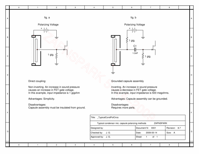
Here is a diagram to help you visualize a couple of ways that capsules are typically "polarized"

TypicalCondPolCircs-1.png


The MXL 603 uses the method shown in fig. b

Cheers.

ZAP
 
abbey road d enfer said:
If the inter-electrode distance is too reduced, the actual signal will not be linear anymore.

Not that the signal is linear, to start with ;), but the linearity as a function of capacitance increase indeed will be worse.

abbey road d enfer said:
The increasd tension on the diaphragm will increase the resonance frequency, which may or may not be of consequence.

It is hard to tell how much the tension will increase and how much it will affect the resonant frequency. It will very much depend on the diaphragm size. For example, the SD will be affected more. Generally, capsules "respond" to the variations in the tuning resonance differently and many are "OK" with some variations. What however is even more important, with the diaphragm getting closer to the backplate the thickness of the air cushion and diaphragm damping properties get completely changed, which depending on the capsule can affect the sound quite significantly. But again, different capsules respond differently.

Best, M
 
777funk said:
abbey road d enfer said:
Nice document, Zap! Is it part of a teaching program?
That is good! Wow!

Thanks. I found that I can't do a good job explaining "polarizing" (or "biasing") a condenser
mic. capsule without drawing a diagram. I decided to do the drawing a bit better.
The feedback I'm getting is that this helps.

Cheers.

ZAP
 
your explanation was excellent zapnspark!
if i wanted to lower the voltage, would a simple resistor in line to the positive lead to the mic back plate be sufficient, or is it a cascade of changes?
 
i was told that rode ntk runs a little high, around 77v, but the capsule i'm looking to replace it with, was recommended 60v, wondering if i could drop a resistor some where in line as my electronics understanding is low.
 
You just repeated your initial question / assumption, while seemingly ignoring the idea / question i posed.

Any trimpots in there, perhaps? Or any chance you could trace out the schematic of the circuitry inside the mic?
 
i found this. i couldnt understand if my life depended on it. i can replace the capsule, i can solder in new leads. if there is a voltage discrepancy, and it could be solved with a 1 or 2 components i can do that to. the math behind it though, no clue.rode ntk schematic.JPG
 
So the good folks at Rode spent many hours working this out, but you, with no technical knowledge, think you can do better?
Talk about an optimist! Just leave it as it is, and use it to make music.
 
R4 and R5 form a voltage divider where the polarization voltage for the capsule
Vpol = -V (pin6) R4 / (R4 + R5), it is currently
Vpol = 125 * 3.3 / (3.3 + 2.2) = 75V.

If you change R5 to 3M3, then that voltage will be 125/2 = 62.5V which I believe is acceptable for your new capsule. Or you can change R4 to 2M2. This calculation is valid if this schematic is correct.
 
Late to this party. Great info. Thanks.
I note the current NTK has both the K2 psu and mic pcb.
It appears to be no drama? to ad a 100k pot, and a double sided capsule.
 
Late to this party. Great info. Thanks.
I note the current NTK has both the K2 psu and mic pcb.
It appears to be no drama? to ad a 100k pot, and a double sided capsule.
A friend did this mod for me.
 

Attachments

  • Peluso-rode-1.jpg
    Peluso-rode-1.jpg
    113.8 KB
  • Peluso-rode-PSU-pot.jpg
    Peluso-rode-PSU-pot.jpg
    354.6 KB
  • laser_label_.jpg
    laser_label_.jpg
    573 KB

Latest posts

Back
Top