


Not having a tube tester, I searched around for a simple test for gm or transconductance.
This is how it works:
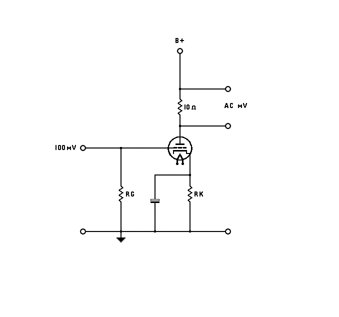
You set the tube up under test as the attached diagram, but instead of the normal plate resistor you sub a 10 ohm resistor.
If your plate voltage should be 100V in your circuit then adjust B+ until the plate is 100V. The grid and cathode resistors should be whatever is correct for your proposed circuit. Gm is directly affected by the current through the tube and the cathode voltage so make sure they are what's required.
Method:
Apply a 100mV sine wave to the grid and measure the ac mV across the 10 ohm resistor with a DMM, The reading will be your gm.
Here's an example of a triode wired EF85. I wanted to check it at 10mA current, so I set it up with a 200 ohm cathode resistor with Vk= 2V. With 100mV input, there was 6mVacross the 10 ohm resistor. 0.006V/0.1V =.06V/V. .06V/10ohms = 6mA/V, which is the gm.
The reason that only 10 ohms is used, is so that the rp of the tube cannot affect the measurement. The rp is in parallel with the plate resistor but 10 ohms is too small to be affected by the rp of any normal tube.
You can also find the rp and mu afterwards by adding a normal plate resistor and finding the gain with the B+ adjusted so that the plate voltage is the same as for the gm test. The gain divided by the gm gives you the value of RP//rp, you can find the rp on a calculator by M- reciprocals. Then gm x rp = mu.
Best
DaveP
