Racking a Studer 928 Channels

GroupDIY Audio Forum

Help Support GroupDIY Audio Forum:

This site may earn a commission from merchant affiliate links, including eBay, Amazon, and others.

smilan

Well-known member
Joined
May 29, 2017
Messages
502
Hi,
I would like to rack two Studer 928 Channels.
I'm thinking of using this PSU:
https://www.jlmaudio.com/shop/power-plant-kit.html?display_tax_prices=1
Now I have few questions:
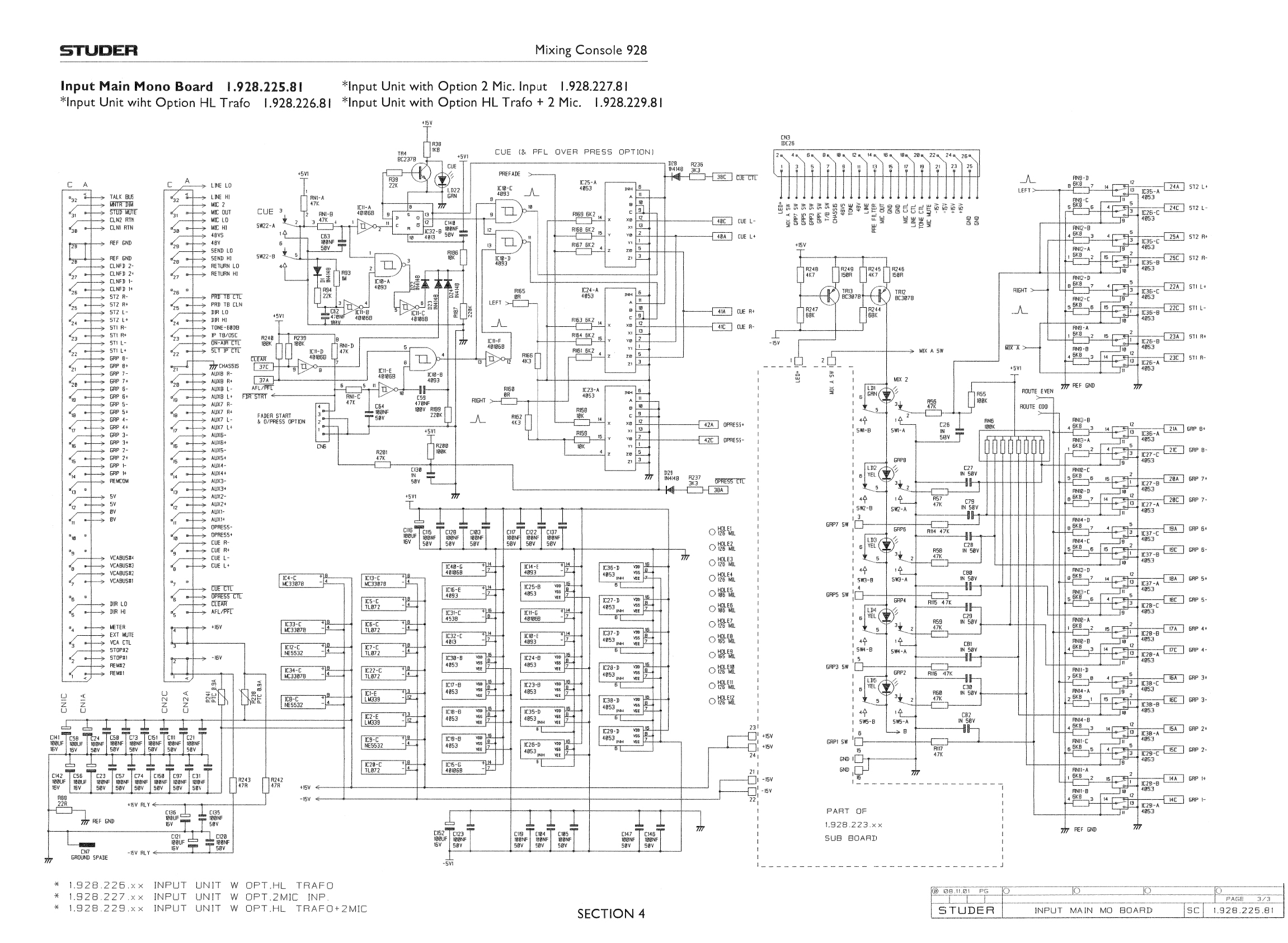
1. Can I connect the 0V to pins 11 and 11A, +16v to pins 3 and 4, - 16V to pins 1 and 2 and the phantom (+48V) to to pins 29 and 29A (all ta CN2) and expect the circuit to work?
2. 48Vs means the 0V reference for the +48V?
3. Can I keep the 5V (pins 12 and 12A on CN2) disconnected or the 5V is crucial for the circuit to work?
4. Is it possible to find a 64 pins connector with solder lugs?
Or it would be easier to solder the voltages and signal wires directly to the PCB?
Search-through-700-000-manuals-online-and-download-pdf-manuals.jpg


smilan said:
1. Can I connect the 0V to pins 11 and 11A, +16v to pins 3 and 4, - 16V to pins 1 and 2 and the phantom (+48V) to to pins 29 and 29A (all ta CN2) and expect the circuit to work?

I think pin 11 and 11A on conncetor 1 are for the 0V reference of the 5V supplie, which should be a different PSU and isolated from the +-16V and +48V PSU. At least it was like that in the 900 series if I remember correclty

smilan said:
2. 48Vs means the 0V reference for the +48V?

I really don't know, hard to tell. Better to check the proper schematic for the 48V circuit.
I would think the 0v reference for the 48v would be the same as the one used for the +-16V

smilan said:
3. Can I keep the 5V (pins 12 and 12A on CN2) disconnected or the 5V is crucial for the circuit to work?

I think you need the 5V circuit, but it's pretty easy to test it out with and without the 5V supply.

smilan said:
4. Is it possible to find a 64 pins connector with solder lugs?

I think those connectors used by Studer are still being made and easy to find on the web.
There's threads here in groupdiy about it

smilan said:
Or it would be easier to solder the voltages and signal wires directly to the PCB?

More elegant to have the proper connector, dont you think so?
 
Thank you Whoops, I guess it will be more simple to use a 4 rails PSU for this project and supply a 5v to the circuit.
As far as the connector, this is the one I should be looking for?
https://www.erni.com/en/products-and-solutions/detail/384617/
 
smilan said:
As far as the connector, this is the one I should be looking for?
https://www.erni.com/en/products-and-solutions/detail/384617/

I don't personally know, but do a search around here on studer connectors, I remember someone replied to me at some point with the studer connectors I needed.

I think those are 64-pin DIN 41612 “eurocard” connector
 
Hello

Whoops said:
I think those are 64-pin DIN 41612 “eurocard” connector

Yes, studer mainly use 41612 since the 80', but can't be sure for this rebranded soundcraft.
Schemo show row A and C, its probably a 96pin (3row) without pins at middle row ?

Best
Zam
 
Back
Top