Raytheon RR30

GroupDIY Audio Forum

Help Support GroupDIY Audio Forum:

This site may earn a commission from merchant affiliate links, including eBay, Amazon, and others.

Conviction

Well-known member
Joined
Mar 27, 2013
Messages
318
Location
Sweden
Hi everyone,

I've had this Raytheon RR30 preamplifier for a couple of years now and finally decided to do a fresh rebuild. I've been keeping it original (except for the electrolytics), but it's always been acting weird with random interference issues, noises, sudden hum tendencies etc. Might be all those carbon comps acting up.

I've never really used it for recording, which of course is a shame. So it's about time.

Attached is the schematic to which I've added the component values. Originally, the schematic had component numbers and a component list. Pretty impractical, plus I'm not sure it's correct.

I would really appreciate if someone would care to take a look at the schematic. At the moment, the output stage hums rather loudly, which lead me to believe I've made an error. Thing is I can't find it.

I've only used metal film resistors, fresh electrolytics and nos Dubilier paper coupling capacitors (.1's and the .022 @400VDC).

I'm not using its original power supply (110V), but a recently overhauled lab supply, confirmed to be free from issues.
DC heaters.

Best,
Olle
 
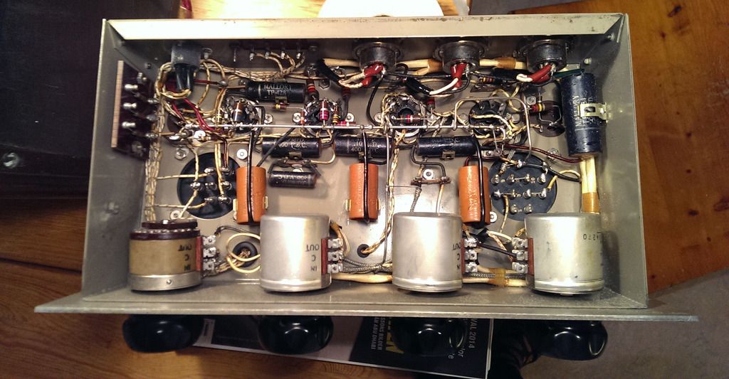
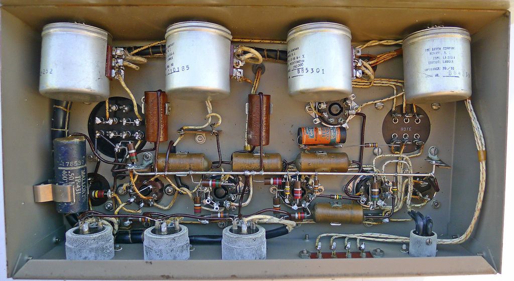
Here's a couple of shots of the inside (the top one is mine, the other I found on the net).
I've kept the layout as close as possible to the original. I'll post a couple of shots of the build later.

The bus bar, though, is originally grounded at the input transformer. B- is connected to the bus bar at the power input terminal, thus travels a rather long distance to chassis connection. Time to change?

Perhaps it would be gainful to redo this, i.e. move the only chassis connection to the output transformer ground or ground of first filter cap, which is very, very close to the input power terminal.

RR30-guts_zpskkltb5e3.jpg


RR30-guts-2_zpsf3ytsvbz.jpg
 
Conviction said:
The bus bar, though, is originally grounded at the input transformer. B- is connected to the bus bar at the power input terminal, thus travels a rather long distance to chassis connection. Time to change?
looks proper.  B- to chassis near the preamplifier input. 
ensure one side of the DC heater supply is connected to B-  .
you show a unbalanced phone jack as your output connection.
somehow, you need to connect the preamplifier common/chassis to your console/a2d/listening device. 
how about a 3 pin XLR ?
 
Hum I'd expect to find related to a poor socket or grid cap contact, if all else is right. 

I doubt Raytheon screwed up the layout. 

Have you ditched the 3->1 mixing bus and rewired a single mic input directly to the input transformer?  You should.  Those type mixing busses present a matched load to each mic and then also have 3->1 mic level mixing losses before you ever see gain. 
 
gridcurrent said:
looks proper.  B- to chassis near the preamplifier input. 
ensure one side of the DC heater supply is connected to B-  .
you show a unbalanced phone jack as your output connection.
somehow, you need to connect the preamplifier common/chassis to your console/a2d/listening device. 
how about a 3 pin XLR ?

I'll leave it as it is then!

No, that's the monitor jack. The output terminal is also shown in the schematic.

The Cannons are gone. I actually found a couple of those round xlr's jacks, and they fit perfectly.

Photos coming up soon.
 
PRR said:
If it is on a "lab" supply, with DC heat, where can hum come from?

I assume a human error. Do you notice anything weird in the schematic? I've crossed checked it with other schems and tube data sheets, but nothing beats a fresh pair of eyes.

I don't know if I made it clear in the previous post, but the component list was torn and faded (original), thus needed some detective work. Some of the resistors were hard to identify, since the color code was faint.
 
emrr said:
Hum I'd expect to find related to a poor socket or grid cap contact, if all else is right. 

I doubt Raytheon screwed up the layout. 

Have you ditched the 3->1 mixing bus and rewired a single mic input directly to the input transformer?  You should.  Those type mixing busses present a matched load to each mic and then also have 3->1 mic level mixing losses before you ever see gain.

Hi Doug.
Do you notice anything weird in the schematic? As I wrote above, I've done my best cross-checking it with other preamp schems and tube datasheets.

I'll check the sockets again. I guess I should have put them in the ultrasonic cleaner instead of using cuetips and isoprop.

I'll check the grid caps too. I know some versions have an extra wire from the grid caps to ground.
Thing is, I've shorted the grid of the first and second 6J7, and isolated the hum to the output stage.

Agreed. I doubt Raytheon screwed it up. The error is surely on my end.

Yes, I ditched the passive 3-1 mixing input shortly after you made me aware 3 or 4 years ago. The input is wired directly to the xformer.
 
mjrippe said:
Posted full manual in the Tech Docs section: https://groupdiy.com/index.php?topic=49653.msg827972#msg827972

That's my copy  8) Thing is, I'm not sure I got the component list correct. The original paper was, to say the least, whiten.
Did you have time to confirm when you worked the unit that came into your shop?

However, I'm pretty sure that the problems I'm experiencing are related to the bench PSU.
When I wrote "free from issues" I took for granted that someone at the shop actually measured it up while overhauling it.
I can see a fair amount of ripple on the output.  :'(
 
PRR said:
Schematic nothing strikes me odd.

That's a start, thanks!

What's the advantages/disadvantages of 6J7 triode versus pentode mode here? I almost thought I had it wrong (taking for granted that 0.47 was the output cap, pins 3/4/5 joined, cathode to ground via C1/R1), before I realized. RCA BA2C fooled me. Then I got fooled again by the RCA OP6.

I'm still unsure of the sonic differences, if any. Gain? Would anyone care to elaborate?
 
I'd be tempted to make stage one triode for purely gain reasons.  Anything modern/loud will overload that stage, you'll get away with fewer instances of input padding in triode.  As-is it's designed for speech with low output mics.  If you do that primarily, you might leave it as-is. 

Sound....in the ear of the beholder....I like triode clipping over pentode clipping if you tend to hit the input hard.  That can depend on the source too.    Gain practicalities vastly overrule.
 
Conviction said:
That's my copy  8) Thing is, I'm not sure I got the component list correct. The original paper was, to say the least, whiten.
Did you have time to confirm when you worked the unit that came into your shop?

Ha!  Sorry, I didn't make the connection there.  The one I had included the original power supply and everything worked fine once I brought it up on a variac, so I didn't end up doing any work on it besides cleaning and testing. 
 
> triode versus pentode mode

Why not make it Pentode end to end?

How much gain can you stand??

Two triodes to an output stage makes a guitar amp. I don't see why you would want more gain after the Volume control. It would hiss even full-down.

Yes, they bought a pentode and didn't use it that way. 6J7 is a very sweet triode too, and SO widely used that any shop would be sure to have spares.
 
I have a couple Raytheon RR-10s here. At least one of them (the one on the bench now with hum issues), has the first 6J7 wired as triode. It has a 10k dropping resistor rather than 47k, as seen in RR-30 manual.
 
Back
Top