>
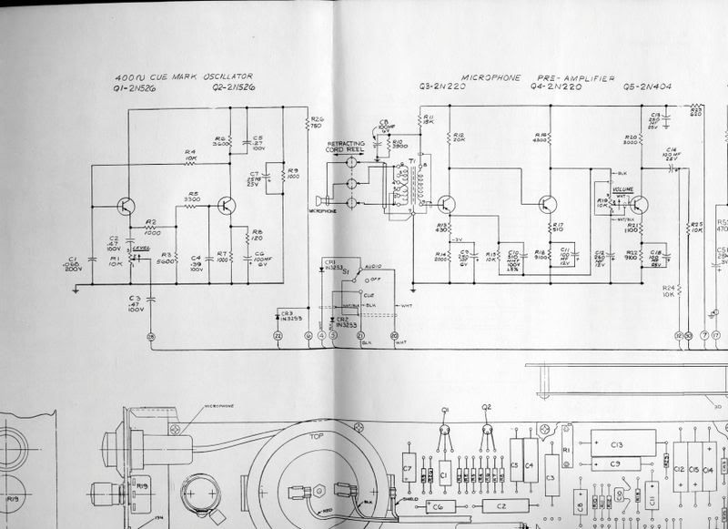
the schematic posted is only partial.
I know.
>
it gives the voltage to pin 7 as being -20v.
I would believe RCA more than me.
A 12VAC transformer, FWB, 1,000uFd, 220R, 1,000uFd power supply would give about the right voltage clean enough for testing.
Three 9V batts would run several hours, and if you screw-up the connections the batts may not be able to smoke anything.
>
2N220 datasheet states recommended voltage is 22v...
DATA sheets don't usually "recommend"; and the one I found said 10V max. That does not contradict 20V supply: the enormous emitter resistors soak-up most of the supply voltage. Also the "10V" rating is probably low-balled, parts like these were 99% sure to be good for 15V or 35V, but the sorting would turn up a few low-volt parts which could still be sold under the 2N220 number.
The input impedance is generally good. If we agree it may be a 1:3 ratio transformer, the actual input Z is 1K or higher, just like we want for most dynamic studio mikes.
The output is unbalanced and 3K (plus any 10K resistor). This will feed all your unbalanced inputs, and most modern balanced inputs, but not a vintage true-600 input. (The Volumax may be true-600.)
Anybody know? Can you still get the BIG Germanium devices used on Delco radios? One of them, or even a solid 200mW device, plus a 470R resistor, could put OK levels in 600 loads.
Jack has a couple popular 150mW Ge parts, the 2N404 and the 2N1309: http://www.muzique.com/pcb.htm
SurplusGizmos has a box of the '404: http://www.surplusgizmos.com/2N404A-PNP-Germanium-Transistor_p_1352.html
Use 'em after C14 like this:
Trim R2 to get 6V to 9V at Collector. If you can get
good thermal contact to cool the transistor, do it. The '404 is handy IF you can still get TO-5 heatsinks. The older Ge-part cases were odd sizes. We used to bend scrap copper heat-clamps to hold these things to chassis; be sure you get good all-round contact, and do not crush the case (white stuff leaks out, no good).
>
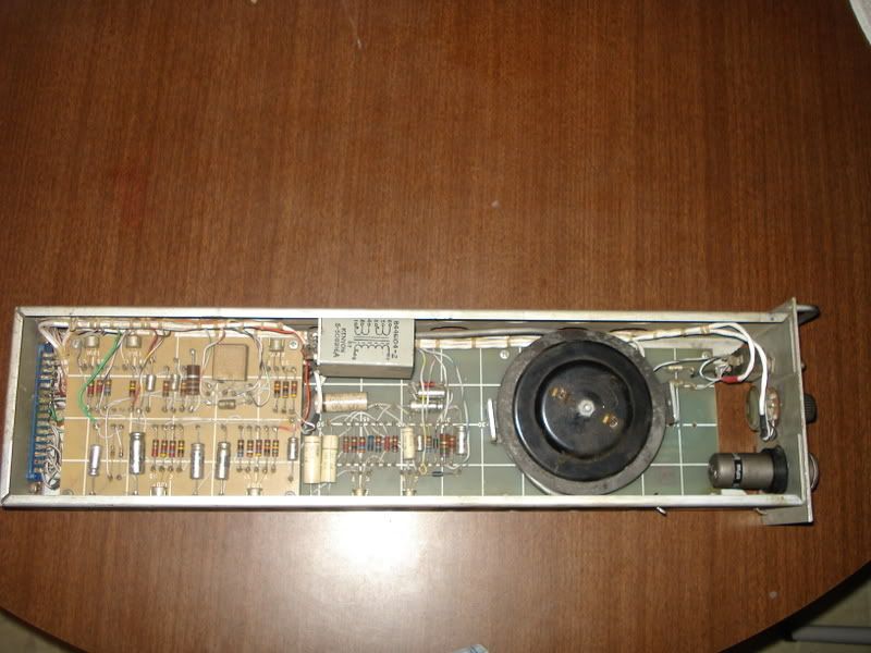
The cable on the reels is pretty rotten
That's sad. That's the part that tickles my fancy.