RJ-47's and audio

GroupDIY Audio Forum

Help Support GroupDIY Audio Forum:

This site may earn a commission from merchant affiliate links, including eBay, Amazon, and others.

boji

Well-known member
Joined
Jan 6, 2010
Messages
2,377
Location
Maryland, USA
Hello,

I'd like your opinions on using M/F RJ-45 connectors to move signals in and out a PCB.
The other end of the cables would be soldered to the backs of xlr/trs jacks or edge connectors like you would see inside an old modular console.
Some I/O would be running to patch panels located about six feet down the chassis. I would be using one female RJ45 jack per balanced signal on the card.

Assuming audio grade wire was used, pinout would be as such:

Pins 1&2 Hot
Pin 3 Null
Pins 4&5 Gnd
Pin 6 Null
Pins 7&8 Cold

Do you think this would sound any worse than say, joining all the O/I out to a single 15pin d-sub connector?

As you know, D-subs encapsulate the pins whereas RJ-45 female pins just sit on the male pad, so I don't know if signal integrity would be an issue.
Also RJ45's use that nifty and quick solderless press tool and plugs that have anti-corrosion gel inside to 'seal' the crimp, but that's not as good as beads of solder.

Might using RJ45's lead to signal loss, poor connection quality or other audio problems?

Thanks for your input!
-Don
 
I've used loads of RJ45 connectors for some high spec. audio work.
The secret is not to buy cheapo product from China/India.
Buy good product from Ossi or Stewart for example, and use a GOOD quality crimp tool.
Screened/unscreened connector 'harmonicas' are available up to 8 ways. Maximum conductor size is
limited to 26 Awg. What's stopping you?

Frank B.
 
Works great. Been using it for years in high end facility build projects. Somef these wires have been in service for 10+ years and keep passing quality signal.
Four channels of analog per cat5. Typically 1 or 2 though in broadcast installs. AES get's you 8 channels and works great as well.
You don't need to get an iron out to make your cables and they are pretty economical.
Stranded STP cat5 with shielded RJ45 plugs/receptacles is recommended but in practice not necessarily required.

Orange/White = Ch1 +
White/Orange = Ch1 -
Grn/White = Ch2 +
White/Grn = Ch2 -
Blue/White = Ch3 +
White/Blue = Ch3 -
Brn/White = Ch4 +
White/Brn = Ch4 -
Shield = Shield

There are some conventions where the Blue/Brn pairs may be used for +/- voltage or signaling but CAT5 is great stuff.

Scraps also make nice cheap hook-up wire that is pretty easy to work with. So don't chuck it!

Soldering cat5 to DB25's is almost fun!

Cheers,
jb
 
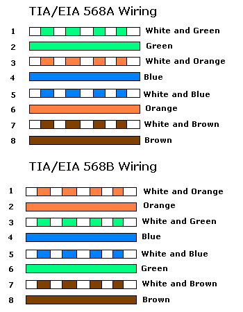
Here is a picture of the standard way of cabling used in ICT. (all around the world, so please do not 'invent' something new)

The 4 sets are twisted and it is best to keep a channel per twisted-pair.
Pin 1-2, 3-6, 4-5, 7-8 are twisted-pair sets. (be ware of the 3-6 and 4-5 pairs location!)

There are various grades of (standard) cable:
Please use STP cable for audio, this cable has shielding per twisted-pair, like a normal audio multi-core cable.
STP-CAT5E / STP-CAT6 patch-cables are widely available and relative cheap (almost no sense in making your own).
Second best is FTP-cable (one foil shield) and last is UTP (no shielding = common computer cable)

For installation purposes there is a lot on the market in patch-fields and sockets. (Panduit for instance)
Cable can be stranded (often used for patch-cords) or solid (used for installation). Your sockets and connectors must be chosen to match the cable.

A good stripping and crimping tool is essential for success (and some starter patience, after a few hundred you will get the hang of it...)

Theo

EDIT: Picture deleted, the 568b picture from 0dbfs next post is the correct one.
 
The above pinout is incorrect for 568b.

This is correct:
cat5_color.gif


Best Regards,
jonathan
 
Everyone, thank you for the replies!

Maximum conductor size is limited to 26 Awg. What's stopping you?
I seem to be getting a unanimous 'yes' about using them, so nothing I guess!

It's a huge bonus to be able to run audio through the actual cat 5 cabling- if it's true that cat5 can sound just as good as standard shielded audio cable, well then that saves me a fairly substantial amount of money.
If anyone thinks there is a better alternative please let me know- I had the opportunity to raid a computer superstore's server room (compusa) when they were going out of business, so I have literally hundreds of patch cables available to strip and use for whatever!

Four channels of analog per cat5. Typically 1 or 2 though in broadcast installs.
Would you mind describing the pinouts for the 2 channel connectors? Thank you.

Your sockets and connectors must be chosen to match the cable.
Thanks I did not know there were different types of crimp connectors!

Here is a picture of the standard way of cabling used in ICT. (all around the world, so please do not 'invent' something new)
Right, I'm not trying to invent a new standard, I thought doubling the pins for signal might ensure better connection, but it sounds like overkill now, after the advice I am getting from you guys.

Here's an example of a single xlr to RJ45 pinout. http://www.tmb.com/Pdf/CpointXLRJ45-A4-web.pdf

I like the idea of using those extra pins for a stronger cold signal.

 
I think this clinches it for me. Thanks again guys.

http://www.studiohub.com/PDF/Technology.pdf

http://www.studiohub.com/PDF/QA.pdf
 
During the "2000's", I designed/built/installed more than a few intercom systems for TV Broadcast facilities.  RTS and Trilogy were the "go to" brands for those installs, and all had RJ-45 connector as options. 

To feed the belt packs and "wall panels" and "rack panels", each intercom company had their own "protocols" for the 8 pins on a RJ-45 as well, as on the XLRs to the belt packs.  However, I ALWAYS had to feed a "mix minus" (or whatever) in/out of the intercom system...again, via RJ-45 connectors.  Hence, I made up more than a few, custom "odd-ball" patch panels that were RJ-45 to XLR...using "factory made" (stranded cable) "cat 5" patch cables that I cut in half, then soldered.  Examples:

http://www.brianroth.com/pix/cleanskies/Img_9789a.jpg

http://www.brianroth.com/pix/cleanskies/Img_9791a.jpg

But, those were nominally +4 dBu I/O....not mic levels!

INDEED...you MUST use the correct RJ-45 connector to match the sizing, stranding, etc of the cable that is crimped!!!!  RJ-45's are sold for solid and stranded wire OF THE CORRECT GAUGE....do NOT use the wrong connector!

IOW, don't expect ANY random piece of Mogami or Belden or Gepco or Canare to correctly crimp into ANY RJ-45.

The intercom systems had no noise pickup problems, but (I'm An Olde School Boi...LOL), I dunno how well cat 5 works for a mic line that is carrying the low level signal from a ribbon mic which is located 200 feet away from a piccolo soloist, down 500' of cable, and then running into a mic pre running 70/80 dB of gain!  lol

Ehhhhh.....with most modern studio levels, it probably works well!

Steve Lampen at Belden sez it will all work. 

Dunno...never tried!

Best,

Bri
 
I Suggest you take look at the PEO (Power Over Ethernet) standard as well.
POE is used to remotely power switches, wifi devices, camera's etc.
It could be a fine (and better!) alternative for phantom style powering. I memory serves me well we can go up to 36W per CAT cable...
Imagine your remote mic-preamp with line-out-level and power-supply over the same CAT cable as a concept.

There are 2 POE standards where 1 is the main standard, it utilizes 2 pairs to distribute power.

grT
 
Four channels of analog per cat5. Typically 1 or 2 though in broadcast installs.
Would you mind describing the pinouts for the 2 channel connectors? Thank you.

http://www.studiohub.com/
These guys have a bunch of broadcast products they have designed around the cat5 cabling spec. They have their own pinout which they have standardized across the product line. Like Brian explains, ot could be anything.

NOT recommended for mic level signals though.

CAT5 is a very useful cabling tool however you can get into "dongle-hell" pretty quick. You can also use an RJ21 connector (50 pins / 25 twisted pairs) with multipair-cables rated for cat5 spec to make intra-area cabling a bit quicker and easier.

I have worked in, installed, and designed numerous broadcast studios using cat5 for AES and analog audio. Never have used it in a recording/production studio though as a primary infrastructure audio cable though I see no reason why it wouldn't work great. Mogami multipair is pretty expensive. Other brands aren't necessarily cheap either.

An analog/aes hybrid multitrack and multichannel studio environment may see great savings using a cat5 cabling system but you should make sure to budget for appropriate connectors, dongles, termination-patchbays, punch-blocks, etc... Maybe DIY'ing some generic PCB's with RJ45 footprints and various other standard footprints like DB25, terminal-strips, molex-connectors, etc would add to the savings.

Once you are adequately and properly "connectorized" the cable part is pretty cheap and can be modified fairly easily.

Cheers,
jb
 

Attachments

  • SHUB-PINOUT.jpg
    SHUB-PINOUT.jpg
    18.3 KB · Views: 31
0dbfs said:
Four channels of analog per cat5. Typically 1 or 2 though in broadcast installs.
Would you mind describing the pinouts for the 2 channel connectors? Thank you.

http://www.studiohub.com/
These guys have a bunch of broadcast products they have designed around the cat5 cabling spec. They have their own pinout which they have standardized across the product line. Like Brian explains, ot could be anything.

Cheers,
jb

THX 0dbfs!

Can be a great solution for insert-style based line-level equipment too.
This is a lot of the equipment we build here, like EQ's/Comp/Lim etc..
-> Balanced line-level IN & OUT and +/-15V = bye bye: backplane and gold-plated-PCB's.......
Do they have a standard on which is In/Send and OUT/Return of pairs 1-2 and 3-6?

You could use this as a the backend of a patch-field, providing good star GND for both Audio and Power.
You could use this inside a desk-design to hook up your (flexible) channel processing modules and channel insert's.
Power and connect remote mic preamps.....(we like the XLR cable length to a mic as short as possible anyway...).

Most interesting is the 'unused' pin-5, which could be used as a remote-control link or +48V/Phantom-power.

If you integrate this into your designs, it is such a low-cost platform!

Theo
 
I had not run across the StudioHub stuff until it was posted.  Interesting.  BUT, every manufacturer seems to create their own "standard".  I also see that StudioHub's connections are for AES digital audio, vs analog I/O.

Sidebar:  A Good Friend of mine says "Standards are GREAT...because there are so many of them!"

lol

The original RJ-45 was concocted by Ma Bell for "something or another" in their phone system, eons ago.  It was adopted for 10-BaseT Ethernet connections perhaps 20 years ago.  In that latter design, only two pairs out of four were originally utilized....one twisted pair for "send" and the second pair for "receive" of digital signals intended for Ethernet connectivity.  POE was an add-on/"hack"...in a similar way that the 500 format edge connector was hacked/expanded into the 51x.  Similar add-ons/hacks were also done for MIDI.

I need to look back through my notes to see if RTS and Trilogy used the same analog RJ-45 in/outs for their intercom interfaces.  But, even if they used the same pin-outs for the analog I/O via RJ-45, that makes them a "sub set" of the entire pro audio "universe", since the connections were used mainly/only(???) for high-end intercom systems in video production facilities.

I have not seen any "standards" for RJ-45 connectors in any analog or digital format.

Best,

Bri
 
I personally hate these type of connectors for anything that will be plugged and unplugged somewhat frequently as the connectors tend to break. Seems like a real pain to wire DIY too unless you have the proper tooling. However I imagine the audio integrity should be fine. The Speck X-sum uses it on the back to connect to the breakout box.
 
connectors tend to break
Those tabs do go easily. The ones with a boot free you to pull it through a nest of other wires without catching and breaking the tab.

Seems like a real pain to wire DIY too unless you have the proper tooling.
Were it not for the ease with which these connectors are made/crimped/connected, the cat5/6 standard would not even be an option for me. :)

I enjoy making my own custom cable lengths on the spot for clients' homes and offices. It really is a quick and fairly error free procedure once you have done it a few times and get a feel for the crimper. Way faster than soldering. Healthier too.
 
john12ax7 said:
I personally hate these type of connectors for anything that will be plugged and unplugged somewhat frequently as the connectors tend to break. Seems like a real pain to wire DIY too unless you have the proper tooling. However I imagine the audio integrity should be fine. The Speck X-sum uses it on the back to connect to the breakout box.

Buy prefabricated cables, they are cheap, 'STP' type is preferred.

A good RJ45 crimping-tool is around 100$, spend no less.
Neutrik EZ-RJpro is good quality http://djdj.nl/cat/l/ne32025.jpg
For socket wiring buy a 'punch-down-tool' inserter, it presses down the wire and cuts it to the correct length, they are around 30$.
http://www.electroshop.nl/product_images/o/207/l_lsa__07255_zoom.jpg

grT
 
> The original RJ-45 was concocted by Ma Bell for "something or another" in their phone system, eons ago.

Among other things: the telephone in your house. Do you remember telephones with wires? Into the 1960s they had lugs on the end, the wall-box had screws, and you had to call Ma to have a telephone disconnected.

It may have come in with Princess and other extra-cost phones.

Ma Bell did not replace reliable screws with less-reliable connectors. Remember all repairs used to be free. Dodgy connections are the bane of any large wiring system, Ma was the biggest wire-system in the world, they took reliability seriously.

Of course if you don't get the wire and plugs from Western Electric in its glory days, reliability is not certain.

> unplugged somewhat frequently as the connectors tend to break.

Screw-wired phones might not get disconnected for 20 years. "Customer connected" (modular) was slightly more fleeting, but how often would you update the color of your Princess phone? Or add a new phone? In 1950s-1960s thinking, very rarely.

Yes, they are not XLRs.

> It was adopted for 10-BaseT Ethernet connections perhaps 20 years ago

Oh, heck, I was doing it in 1980, 30+ years?

> only two pairs out of four were originally utilized....

10-speed, true. 100-speed ether specifies 8 wires, the extras tied to ground (through resistance) for hash and impedance control. You kinda need all 8 wires on any non-trivial 100-speed network cable (however they may be diverted to DC and still control the sighal environment).
 

Latest posts

Back
Top