


Hi all,
My first post here, although I've been "read-only" as a non-member for a while. Thanks Ethan for approving and for running this site.
I'm a hobbyist musician and I've built many kits over the years (a few valve amps, some pedals etc). I have an academic background in electronics, but that was 30 years ago so I consider myself at beginner level. I've forgotten lots, but my soldering is still pretty decent.
Having been inspired by some of the threads here and the things you guys build I thought I'd have a go at trying something from schematic rather than kit, doing the layouts myself. As I tend to be doing a little more recording lately I thought I'd go for a preamp and I bought an old back issue of TapeOp that has the Hampton design schematic in it.
There are 3 parts to this project - the main preamp board and 2 power supplies - 1 for the heaters/phantom and other of course for the HT.
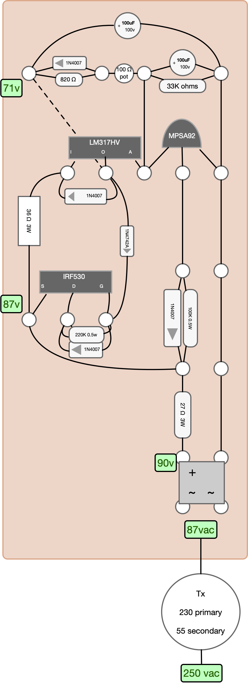
I thought I'd tackle the (50v) heater/phantom supply first as it's the more complex part of the project (for me anyway - first time doing a layout from a schematic). It's designed around a source follower first stage into an LM317.
Here's my layout. My original plan was to post this layout here and ask if anyone would be kind enough to kit the tires of it with me, but it took a while for my membership to get approved so in the end I built this layout (I bought two of everything in case I blow something up") ). I'm not sure if for copyright reasons I'm allowed to post the schematic?
). I'm not sure if for copyright reasons I'm allowed to post the schematic?
I have an immediate issue which is that I'm over-voltage and voltage drops with load, which tells me it's not regulating. I'm not sure if I've blown up the LM317 or if it's going into it's "idiot/thermal protection" mode and shutting down. Whilst I'm pushing more volts into it than the design calls for, the In/Out difference is still well under the spec. 60v (this is the HT version).
Any thoughts welcome on the layout and thoughts on potential issues.
The reason I'm over-voltage is I always believed the UK settled on 230v mains, but I'm measuring 250v at the socket and rather than the expected 55v AC out of the secondary I have more like 87v.
The green labels are what I've measured at this point. If I put it under load (4 x 12v bulbs to simulate the heaters) output drops to about 15v.
I don't have a variac (on Xmas present to self list along with a scope) but I was thinking I could DC test with 5 x 9v batteries if I needed to test with lower overall voltage.
Many thanks for any thoughts - do you think my guess is correct that I've managed to somehow blow up the LM317? Could be thermal damage from soldering I guess.
My first post here, although I've been "read-only" as a non-member for a while. Thanks Ethan for approving and for running this site.
I'm a hobbyist musician and I've built many kits over the years (a few valve amps, some pedals etc). I have an academic background in electronics, but that was 30 years ago so I consider myself at beginner level. I've forgotten lots, but my soldering is still pretty decent.
Having been inspired by some of the threads here and the things you guys build I thought I'd have a go at trying something from schematic rather than kit, doing the layouts myself. As I tend to be doing a little more recording lately I thought I'd go for a preamp and I bought an old back issue of TapeOp that has the Hampton design schematic in it.
There are 3 parts to this project - the main preamp board and 2 power supplies - 1 for the heaters/phantom and other of course for the HT.
I thought I'd tackle the (50v) heater/phantom supply first as it's the more complex part of the project (for me anyway - first time doing a layout from a schematic). It's designed around a source follower first stage into an LM317.
Here's my layout. My original plan was to post this layout here and ask if anyone would be kind enough to kit the tires of it with me, but it took a while for my membership to get approved so in the end I built this layout (I bought two of everything in case I blow something up
). I'm not sure if for copyright reasons I'm allowed to post the schematic?
I have an immediate issue which is that I'm over-voltage and voltage drops with load, which tells me it's not regulating. I'm not sure if I've blown up the LM317 or if it's going into it's "idiot/thermal protection" mode and shutting down. Whilst I'm pushing more volts into it than the design calls for, the In/Out difference is still well under the spec. 60v (this is the HT version).
Any thoughts welcome on the layout and thoughts on potential issues.
The reason I'm over-voltage is I always believed the UK settled on 230v mains, but I'm measuring 250v at the socket and rather than the expected 55v AC out of the secondary I have more like 87v.
The green labels are what I've measured at this point. If I put it under load (4 x 12v bulbs to simulate the heaters) output drops to about 15v.
I don't have a variac (on Xmas present to self list along with a scope) but I was thinking I could DC test with 5 x 9v batteries if I needed to test with lower overall voltage.
Many thanks for any thoughts - do you think my guess is correct that I've managed to somehow blow up the LM317? Could be thermal damage from soldering I guess.